Input
Amplifier
•
Setup
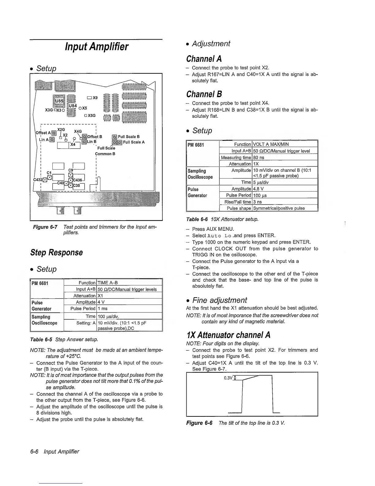
Figure
6-7
Test points and trimmers for the Input am-
plifiers.
Step
Response
•
Setup
PM 6681
Function TIME A-B
Input A+B
50 Q/DC/Manual trigger levels
Attenuation X1
Pulse
Amplitude
4V
Generator
Pulse
Period 1 ms
Sampling
Time
100
ps/div.
Oscilloscope
Setting: A 10 mV/div.
(10:1
<1.5
pF
passive
probe), DC
Table
6-5
Step
Answer setup.
NOTE: The
adjustment
must be made at an
ambient
tempe-
rature of
+25°C.
-
Connect the
Pulse Generator to the A input of
the
coun-
ter
(B
input)
via
the
T-piece.
NOTE: It
is
of
most
importance that the
output pulses from the
pulse
generator
does
not
tilt
more
that 0.1% of the pul-
se
amplitude.
-
Connect the
channel A of the oscilloscope via
a probe to
the other
output from the T-piece, see Figure
6-6.
-
Adjust the
amplitude of
the oscilloscope until the pulse is
8 divisions high.
-
Adjust the
probe
until the pulse is
absolutely
flat.
•
Adjustment
Channel
A
~
Connect
the probe
to
test
point X2.
-
Adjust
R167=L1N A and
C40=1X
A
until
the signal is ab-
solutely flat.
Channel B
“
Connect
the probe
to test
point X4.
-
Adjust
R168=L1N B and C38=1X B until
the signal
is
ab-
solutely
flat.
•
Setup
PM 6681
Function
VOLTA MAX/MIN
Input
A+B
50 n/DC/Manual trigger level
Measuring
time
80 ns
Attenuation
IX
Sampling
Oscilloscope
Amplitude
10
mV/div
on
channel B
(10:1
<1.5 pF passive probe)
Time
5
iis/div
Pulse
Generator
Amplitude 4.8
V
Pulse Period
100
us
Rise/Fali time 3 ns
Pulse shape
Symmetrical/positive pulse
Table
6-6
1 0X Attenuator
setup.
-
Press
AUX MENU.
-
Select Auto
Lo .and press
ENTER.
“
Type
1000 on the numeric
keypad and press ENTER.
-
Connect CLOCK
OUT from the pulse generator to
TRIGG
IN on the
osilloscope.
-
Connect the Pulse
generator to the A Input
via
a
T-piece.
-
Connect the
oscilloscope to the other end of the
T-piece
and check
that the base- and
top
line
of the pulse is
absolutely
flat
•
Fine
adjustment
At the first
hand
the XI attenuation should be best
adjusted.
NOTE: It is of
most imporance that the
screewdriver
does
not
contain
any
kind of magnetic material.
IX
Attenuator
channel
A
NOTE:
Four digits on the
display.
-
Connect
the probe to test
point
X2.
For trimmers and
test points see
Figure
6-6.
-
Adjust C40=1X A
until the tilt of the top line is
0.3
V.
See Figure
6-7.
6-6
Input
Amplifier