“
Remove the probe.
-
Read
the counters
display.
-
Adjust
C40=1X
A until the displayed value has increased
5 to
1
0
mV.
10X
Attenuator
channel A
NOTE: Three digits on the display,
-
Select 10X on input A.
-
Connect the
probe to
test point X2. For trimmers and
testpoints see Figure
6-6.
-
Adjust
C1=10X A and C432
until
best
possible
pulse,
without any overshoots
or undershoots.
“
Adjust C1=10X A
until
the tilt of the top line Is 0.3 V.
See
Figure
6-7.
”
Remove the probe.
-
Read the counters display.
-
Adjust
C40=10X
A
until the displayed value has Increa-
sed
10
to
30 mV.
-
Shift between
IX
and
10X and check that the displayed
value does not differ
more than ±50 mV.
1X
Attenuator channel
B
NOTE:
Four digits on the display,
-
Connect the
probe to test point X4. For
trimmers
and
testpoints
see Figure
6-6.
“
Adjust C38=1X B until
the tilt
of the top line Is 0.3
V.
See Figure
6-7.
-
Remove the probe.
-
Read
the counters
display.
“
Adjust C38=1X B until the
displayed value
has increased
5
to
1 0
mV.
10X
Attenuator
channel B
NOTE: Three digits on the
display.
-
Select 10X on input B.
-
Connect the probe
to test
point X4. For trimmers and
testpoints see Figure
6-6.
“
Adjust C9=10X B and C436
until best possible pulse,
without any overshoots or
undershoots.
-
Adjust
C9=10X
B
until the tilt of the top line is 0.3 V.
See Figure
6-7.
-
Remove the
probe.
-
Read the counters
display.
-
Adjust
C38=10X
B
until the displayed value has increa-
sed 10 to 30 mV.
-
Shift between
IX
and
10X and check that the displayed
value does not differ
more than ±50 mV.
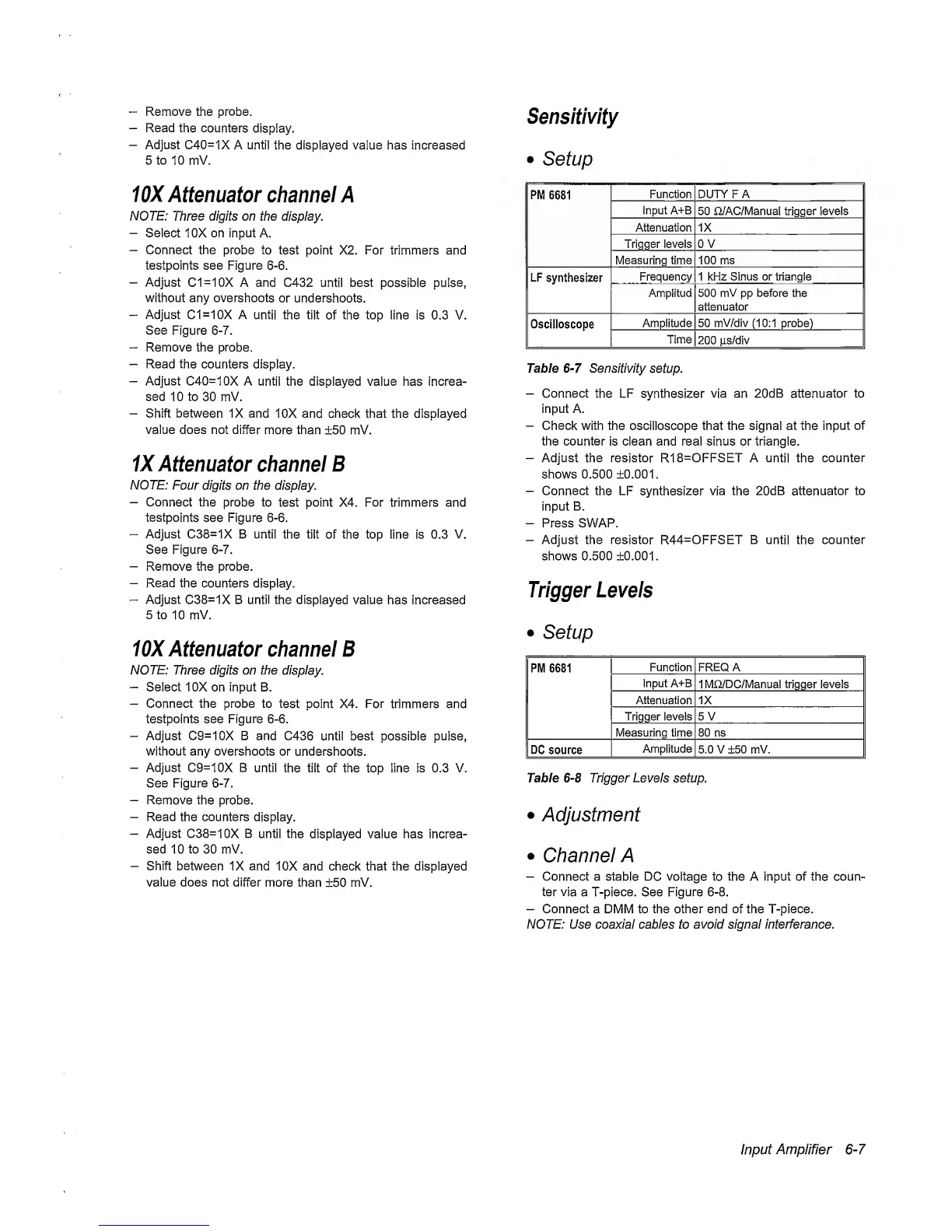
Sensitivity
•
Setup
PM
6681
Function DUTY FA
Input A+B
50 ti/AC/Manual trigger levels
Attenuation IX
Tripper levels 0 V
Measuring time 100 ms
LF synthesizer
Frequency 1 kHz Sinus or triangle
Amplitud 500
mV
pp
before the
attenuator
Oscilloscope
Amplitude 50
mV/div
(10:1
probe)
Time
200
jis/div
Table
6-7
Sensitivity
setup.
-
Connect
the LF synthesizer
via
an
20dB attenuator to
input A.
-
Check with the
oscilloscope
that the
signal at the
input
of
the counter is clean and real sinus or triangle.
-
Adjust the resistor R18=OFFSET A
until the
counter
shows 0.500 ±0.001.
-
Connect
the LF synthesizer via the 20dB attenuator
to
input
B.
-
Press SWAP.
-
Adjust the resistor R44=OFFSET B until the counter
shows 0.500 ±0.001.
Trigger
Levels
•
Setup
PM 6681
Function FREQ
A
Input A+B
1 MCi/DC/Manual
trigger
levels
Attenuation
1X
Trigger levels 5 V
Measuring time 80 ns
DC
source
Amplitude
5.0 V ±50 mV.
Table
6-8
Trigger Levels setup.
•
Adjustment
•
Channel A
—
Connect
a
stable DC voltage to the
A
input of
the coun-
ter via a T-piece. See Figure
6-8.
-
Connect a DMM to the other end of the T-piece.
NOTE: Use coaxial cables to avoid signal interferance.
Input Amplifier
6-7
 Loading...


