Analog
output
DC-source
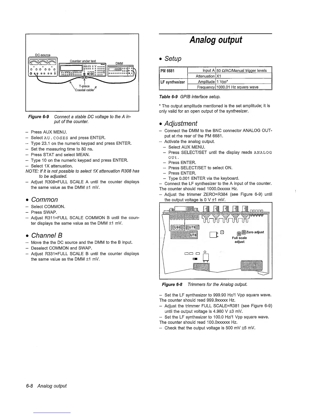
Figure
6-9
Connect a stable
DC
voltage to the A in-
put of the counter.
-
Press AUX
MENU.
-
Select
AU. COdES
and press
ENTER.
-
Type
23.1
on the nunneric
keypad
and press
ENTER.
-
Set the
measuring
time to 80 ns.
-
Press STAT and select MEAN.
-
Type 10 on the numeric
keypad
and press ENTER.
-
Seiect IX attenuation.
NOTE: If it is not possible to
select 1X attenuation
R308 has
to be adjusted.
-
Adjust R308=FULL
SCALE
A untii the counter
dispiays
the same value as the DMM ±1
mV.
•
Common
-
Select COMMON.
-
Press
SWAP.
-
Adjust
R311=FULL SCALE COMMON
B
until
the coun-
ter dispiays the same
vaiue
as the DMM ±1
mV.
•
Channel
B
“
Move
the
the DC source and the DMM
to the B input.
-
Deseiect
COMMON and SWAP.
-
Adjust R331=FULL
SCALE
B untii the counter
dispiays
the same value as
the DMM
+1
mV.
•
Setup
PM 6681
Input
A
50 n/AC/Manual
trigger
levels
Attenuation XI
LF synthesizer
Amplitude 1
Vpp*
Frequency
1000.01 Hz
square wave
Table
6-9
GPIB interface setup.
*
The output amplitude mentioned
is
the set
ampiitude;
it is
oniy vaiid for an
open output of the
synthesizer.
•
Adjustment
-
Connect the
DMM
to the BNC
connector
ANALOG OUT-
put at rhe rear of the PM
6681
.
“
Activate
the
anaiog output.
-
Seiect AUX MENU.
-
Press SELECT/SET until
the
display reads analog
out
.
-
Press
ENTER.
-
Press
SELECT/SET to select ON.
-
Press ENTER.
-
Type 0.001
ENTER via the
keyboard.
-
Connect the LF
synthesizer
to the A input of
the
counter.
The counter
should
read lOOO.Oxxxxx
Hz.
“
Adjust
the trimmer ZERO=R384
(see Figure
6-9)
untii
the output voltage is 0
V
±1
mV.
Figure
6-8
Trimmers for the Analog
output
-
Set the LF
synthesizer to 999.90 Hz/1
Vpp
square
wave.
The
counter
should read 999.9xxxxx
Hz.
-
Adjust the
trimmer
FULL SCALE=R381
(see
Figure
6-9)
until the output voltage is
4.980 V ±3 mV.
-
Set
the LF synthesizer to 100.0
Hz/1
Vpp square
wave.
The
counter
should read lOO.Oxxxxxx
Hz.
-
Check that the output voitage is 500
mV ±5 mV.
6-8
Analog
output