1.3 GHz HF-input, PM 9621 2.7 GHz HF-input, PM
9624
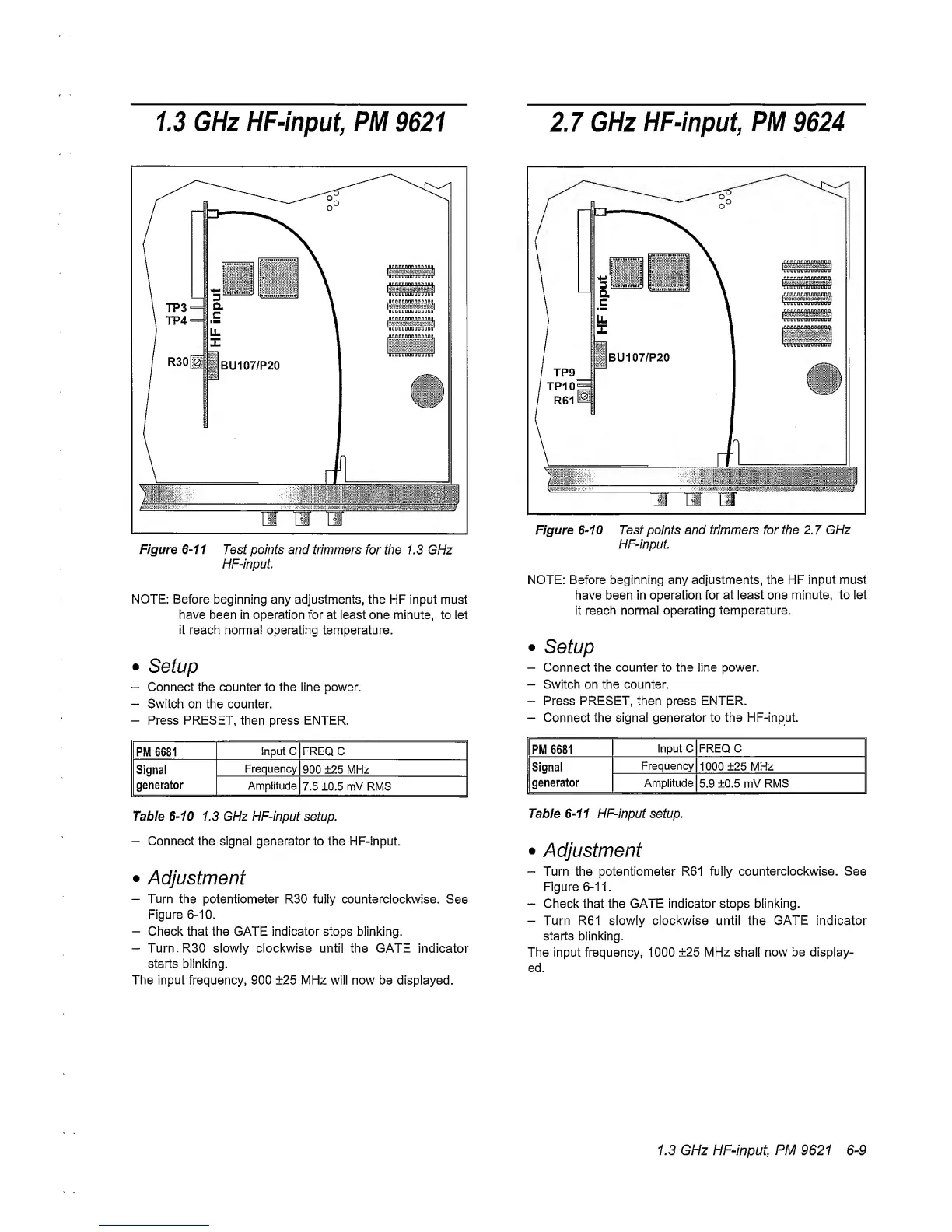
Figure
6~11
Test points and
trimmers
for the 1.3 GHz
HF-input
NOTE:
Before
beginning any adjustments, the HF input
must
have
been in
operation
for at least one minute, to let
it reach normal operating temperature.
•
Setup
~
Connect the counter to the line power.
-
Switch on the counter.
—
Press PRESET,
then
press ENTER.
PM 6681
Input C FREQ
C
Signal
generator
Frequency
900 ±25 MHz
Amplitude
7.5 ±0.5 mV RMS
Table
6-10
1.3 GHz HF-input setup.
-
Connect
the signal generator to the HF-input.
•
Adjustment
-
Turn
the potentiometer R30 fully counterclockwise.
See
Figure
6-10.
-
Check that the GATE indicator stops blinking.
“
Turn.RSO slowly clockwise until
the GATE
indicator
starts
blinking.
The input frequency, 900 ±25 MHz will now be displayed.
Figure
6-10
Test
points
and trimmers for
the
2.7
GHz
HF-input
NOTE: Before beginning any adjustments, the HF
input must
have been in operation for
at least
one
minute,
to let
it reach normal
operating temperature.
•
Setup
-
Connect
the counter to the line power.
-
Switch on the counter.
-
Press
PRESET, then
press ENTER.
-
Connect the signal
generator to the HF-input.
PM 6681
Input C FREQ C
Signal
generator
Frequency
1000 ±25 MHz
Amplitude
5.9
±0.5 mV RMS
Table
6-11
HF-input setup.
•
Adjustment
-
Turn the potentiometer R61 fully
counterclockwise.
See
Figure
6-11.
~
Check that the GATE
indicator
stops
blinking.
-
Turn R61 slowly clockwise until the GATE indicator
starts
blinking.
The input frequency, 1000
±25
MHz shall
now be display-
ed.
1.3 GHz HF-input, PM 9621
6-9