Do you have a question about the Fluke ScopeMeter 190-202 and is the answer not in the manual?
Step-by-step guide on how to power on the test tool using the power adapter.
Procedure to reset the test tool to its factory settings without clearing memories.
Instructions on how to use the test tool's menus to select and function.
Explanation of the illumination LED function for various keys on the test tool.
Details on connecting BNC signal inputs and banana jack inputs for measurements.
Guidance on setting the correct probe types for accurate measurements.
Procedure for selecting the desired input channel (A, B, C, or D) for operation.
How to use the Connect-and-View feature for automatic signal setup.
Instructions on how to perform automatic scope measurements and display readings.
Method to freeze the screen display (all readings and waveforms) at any time.
Explanation of using functions to smooth waveforms and capture events.
Techniques to suppress high frequency noise on a waveform.
How to invert the displayed waveform for a clearer view.
Adjusting input sensitivity continuously for amplitude control.
Methods to reduce noise by limiting bandwidth or using average function.
How to add, subtract, multiply, or plot waveforms using math functions.
Explanation of the Spectrum function for amplitude analysis in frequency domain.
Displaying a reference waveform with the actual waveform for comparison.
Using a reference waveform as a template for testing actual waveforms.
Using analysis functions like Cursors, Zoom, and Replay for detailed waveform analysis.
How to perform automatic meter measurements and display numeric readings.
Displaying present measurement relative to a defined reference value.
Performing multimeter measurements and displaying readings on the meter input.
Procedure for measuring resistance using the test tool.
Steps to set up the test tool for current measurement.
How to activate manual ranging or choose auto ranging for measurements.
Performing relative voltage measurements by obtaining a reference value.
Using the TrendPlot function to plot graphs of scope or meter measurements over time.
Using the SCOPE RECORD function to log waveforms for extended periods.
Viewing recorded data in normal or all view modes.
Automatically stopping recording when deep memory is full.
Using trigger functions to start or stop recording based on events.
Storing and replaying the last 100 most recent scope screens automatically.
Replaying stored screens continuously, similar to playing a video tape.
Obtaining a detailed view of a waveform by zooming in.
Using cursors to make precise digital measurements on waveforms.
Procedure for using horizontal cursors for voltage measurements.
Using vertical cursors for time measurements or RMS measurements.
Measuring rise time using cursors on the waveform.
Optimizing trigger controls for level, slope, and delay.
Displaying waveform before or after a trigger point.
Changing trigger settings for automatic triggering.
Using trigger control for unstable or low frequency signals.
Using trigger filter to reduce jitter on noisy waveforms.
Enabling stable waveform capture for burst waveforms.
Standardizing trigger settings for video signal measurements.
Isolating and displaying specific pulses for analysis.
Setting trigger to identify missing pulses in a train of positive pulses.
Connecting external flash memory or a PC via USB ports.
Saving and recalling screens, setups, and recordings to internal or USB memory.
Saving screens and setups to internal memory or USB device.
Procedure for deleting saved screens and associated setups.
Recalling saved screens and setups for waveform comparison.
Browsing through saved screens and setups in memory.
Steps to connect the test tool to a PC for software use.
Illustrations showing the use of standard accessories like probes and clips.
Utilizing isolated inputs for accurate measurements and safety.
Procedure to adjust display contrast and brightness for optimal viewing.
How to adjust the date and time settings on the test tool.
Tips for conserving battery power and extending operating time.
Configuring auto set behavior for signal frequency and input coupling.
Instructions for safely cleaning the test tool.
Procedure for charging the Li-ion batteries and understanding battery status.
Step-by-step guide for replacing the battery pack.
Procedure to calibrate voltage probes for optimal response.
How to view model, software, and calibration details.
List of user-replaceable parts and optional accessories.
Solutions for common issues like test tool shutdown or screen problems.
Detailed specifications for oscilloscope functions and performance.
Specifications for trigger modes, delay, and pre-trigger view.
Specifications for edge trigger sensitivity and level control.
Specifications for video triggering standards, modes, polarity, and sensitivity.
Specifications for pulse width trigger conditions and adjustment range.
Specifications for auto ranging attenuators and time base.
Capacity and viewing method for automatic scope screens.
Accuracy and performance characteristics for automatic scope measurements.
Specifications for meter measurements on Fluke 190-xx4 models.
Specifications for resistance measurements, including ranges and accuracy.
Safety guidelines, including maximum floating and input voltages.
Accuracy specifications for the 10:1 Probe VPS410.
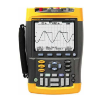
| Bandwidth | 200 MHz |
|---|---|
| Channels | 2 |
| Sample Rate | 2.5 GS/s |
| Memory Depth | 10, 000 points per channel |
| Safety Rating | CAT III 1000 V / CAT IV 600 V |
| Vertical Resolution | 8 bits |
| Timebase Range | 5 ns/div to 2 min/div |
| Display | Color LCD |
| Input Coupling | AC, DC, GND |
| Operating Temperature | 0°C to 40°C |
| Battery Life | 4 hours |




 Loading...