EasyManua.ls Logo

Fluke SPOT Light - User Manual

Fluke SPOT Light
28 pages
Print Icon
To Next Page IconTo Next Page
Loading...
PN 4151274
February 2012 | Rev. 2, 1/22
© 2012-2022 Fluke Corporation. All rights reserved. Printed in USA. Specifications are subject to change without notice.
All product names are trademarks of their respective companies.
SPOT Light
SpO2 Functional Tester
Question and Answer IconNeed help?

Do you have a question about the Fluke SPOT Light and is the answer not in the manual?

Overview

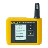
The Fluke Biomedical SPOT Light SpO2 Functional Tester is a compact, portable, functional tester designed to measure the performance of SpO2 monitors (pulse oximeters). It uses light detection and emission to perform tests, examining the electronics of the pulse oximeter and the sensor.

Function Description:

The SPOT Light SpO2 Functional Tester is intended to test and verify the basic operation of patient monitoring devices or systems used to monitor SpO2. It provides an optical signal to verify the electronics inside the pulse oximeter sensor are functional. The device is not intended for use on patients, or to test devices while connected to patients. It is not intended to be used to calibrate medical equipment. The pulse oximeter component of the device is not intended to validate the SpO2 accuracy of pulse oximeter equipment. This device is not intended to confirm the SpO2 accuracy of the calibration curve of the pulse oximeter monitor or to assess the optical characteristics of representative pulse oximeter sensors to determine their proper calibration.

Important Technical Specifications:

General Specifications:

  • Temperature:
    • Operating: 10 °C to 40 °C (50 °F to 104 °F)
    • Storage: -20 °C to +60 °C (-4 °F to +140 °F)
  • Humidity: 10 % to 90 % non-condensing
  • Altitude: 3,000 m (9,843 ft)
  • Size (W x H x D): 12.53 cm x 14.86 cm x 4.77 cm (4.94 in x 5.85 in x 1.88 in)
  • Display: LCD Monochrome display
  • Communication (USB Device Virtual COM Port): Mini B connector for service upload of firmware
  • Power: Lithium-ion rechargeable, 3.7 V, 10.75 Wh battery, 2900 mAh
  • Battery Charger: 100 V to 240 V, 50/60 Hz input, 6V/3A output. For best performance, battery charger must be connected to a properly grounded ac receptacle.
  • Battery Life: 10 hours (minimum)
  • Weight: 0.29 kg (0.7 lb)
  • Safety: IEC 61010-1: 300 V CAT II, Pollution Degree 2
  • Ingress Protection Rating: IEC 60529: IP20
  • Electromagnetic Environment: IEC 61326-1: Basic

Oximeter SpO2 Optical Emitter and Detector:

  • %O2 Saturations: 70 %, 75 %, 80 %, 85 %, 90 %, 95 %, 97 %, 98 %, 99 %, and 100 %
  • Accuracy:
    • With oximeter manufacturer's R-curve:
      • Saturation within UUT specific range: ±(1 count + specified accuracy of the UUT)
      • Saturation outside UUT specific range: monotonic with unspecified accuracy
    • With Fluke Biomedical R-curves:
      • 95 to 100 %: ±(3 counts + specified accuracy of the UUT)
      • 85 to 90 %: ±(5 counts + specified accuracy of the UUT)
      • 80 %: ±(7 counts + specified accuracy of the UUT)
  • Heart Rate:
    • Rates: 30, 40, 60, 65, 80, 100, 120, 140, 150, 180, and 240 BPM
    • Accuracy: ±1 % of setting
  • Transmission (Ratio of detector current to LED current, expressed in parts per million (ppm)):
    • Ratios: Large finger (12.00 ppm), medium finger (80.00 ppm), and small finger (300.00 ppm)
    • Accuracy: +50 %/-30 % for compatible monitors, unspecified for others. Selected by finger size and color: large finger, medium finger, small finger.
  • Pulse Amplitude:
    • Amplitudes: Low (0.2 %), medium (2 %), and high (10 %)
  • Artifact:
    • Respiration: 2.5% of transmission
    • Rate: 20 BrPM
    • Ambient Light Frequency: 50 Hz and 60 Hz
  • Compatible Manufacturer Products:
    • With manufacturer R-curve: Nellcor, Masimo, Nonin, and Nihon Kohden
    • With Fluke Biomedical R-curve: Mindray, GE-Ohmeda, Philips/HP, and BCI

Usage Features:

  • Product Controls and Connections:
    • SpO2 Artificial Finger (Item 1)
    • Scroll Up and Down Buttons (Item 2)
    • Select Button (Item 3)
    • LCD Display (Item 4)
    • Mini B USB Device Port (Service use only) (Item 5)
  • Power On/Off: Push the SELECT button for one second to turn on the Product. The screen shown in Figure 2 is the power-up screen. Push SELECT and hold for 3 seconds to turn off the Product.
  • SpO2 Sensor Placement: Put the sensor with the LEDs on the bottom of the artificial finger. While you put the sensor on the artificial finger, monitor the signal indicator along the bottom of the Product display. Adjust the sensor on the finger for maximum signal strength.
  • Setting Test Parameters: When you turn on the Product, all parameters are set to their default values. To change a parameter value, push the UP or DOWN arrow to move the highlight to a parameter that you need to change. Push SELECT to move the highlight to the value of the parameter. Push the UP or DOWN arrow to scroll through the values. With the correct parameter value shown in the display, push SELECT to set the parameter. Default values are in bold type.
  • Setting Custom Tests: The Test parameter is set to Manual by default. A maximum of three custom tests can be stored in the Product. To set up a custom test:
    1. Push UP or DOWN to move the highlight to Test: in the display.
    2. Push SELECT. The highlight moves to the Test parameter.
    3. Push UP or DOWN to scroll through the test values. Stop when Custom 1, Custom 2, or Custom 3 shows in the display.
    4. Push SELECT. When the Test parameter is set to Custom 1, Custom 2, or Custom 3, each parameter you change becomes a new value for that custom test. By default, the unit automatically turns off if inactive for 5 minutes. To change this setting push and hold SELECT for 3 seconds when the 'Test' field is highlighted. This shows an auto-off option. Select Y for Yes or N for No.

Maintenance Features:

  • General Maintenance: The Product is an SpO2 functional tester. Try to prevent mechanical abuse that could change the test values. The Product has no internal user-serviceable parts.
  • Safety Information for Maintenance:
    • Repair the Product before use if the battery leaks.
    • Remove batteries to prevent battery leakage and damage to the Product if it is not used for an extended period.
    • Connect the battery charger to the mains power outlet before the Product.
    • Use only Fluke approved power adapters to charge the battery.
    • Do not short the battery terminals together.
    • Do not keep cells or batteries in a container where the terminals can be shorted.
    • Keep cells and battery packs clean and dry. Clean dirty connectors with a dry, clean cloth.
    • Batteries contain hazardous chemicals that can cause burns or explode. If exposure to chemicals occurs, clean with water and get medical aid.
    • Do not put battery cells and battery packs near heat or fire. Do not put in sunlight.
    • Do not disassemble or crush battery cells and battery packs.
    • Have an approved technician repair the Product.
    • Use only specified replacement parts.
    • Remove the input signals before you clean the Product.
    • Connect factory supplied three-conductor mains power cord to a grounded power outlet.
    • Do not use a two-conductor adapter or extension cord.
  • Cleaning the Product: Do not put fluid onto the Product surface. Fluid seepage into the electrical circuitry may cause the Product to fail. Do not use spray cleaners on the Product. This action can force the cleaning fluid into the Product and damage electronic components. Clean the Product occasionally with a damp cloth and mild detergent. Try to prevent the entrance of liquids.
  • Battery Maintenance: For peak battery performance, charge the Product to maximum charge a minimum of one time each month. If the Product is not to be used for more than a month, keep it connected to the charger. When the battery gets low, a low battery message shows in the display.
  • Charging the Battery: The battery charge level is shown in the lower-right corner of the display. With the AC/DC power supply removed from the Product, the battery icon shows the charge level. The battery can be charged while it is in or out of the Product. The charge rate is slower when the Product is energized and the battery charger is on. To charge the battery:
    1. As shown in Figure 6, connect the ac/dc power supply to the power connector on the battery pack.
    2. Connect the ac/dc power supply to a power source. The battery charge LED on the battery pack shows red or green when the ac/dc power supply is connected to the battery pack. When the LED is green, the battery is charged. When you have two or more battery packs, you can charge one battery externally while you use the other to energize the Product.
  • Battery Removal: The battery pack is easy to remove and replace. To remove the battery pack:
    1. Push down on the battery pack latch as shown in Figure 7.
    2. Pull the battery pack from the Product. To put the battery pack into the Product, align the battery pack with the guides on the Product and push it into the Product until the latch locks.

Fluke SPOT Light Specifications

General IconGeneral
BrandFluke
ModelSPOT Light
CategoryTest Equipment
LanguageEnglish

Related product manuals