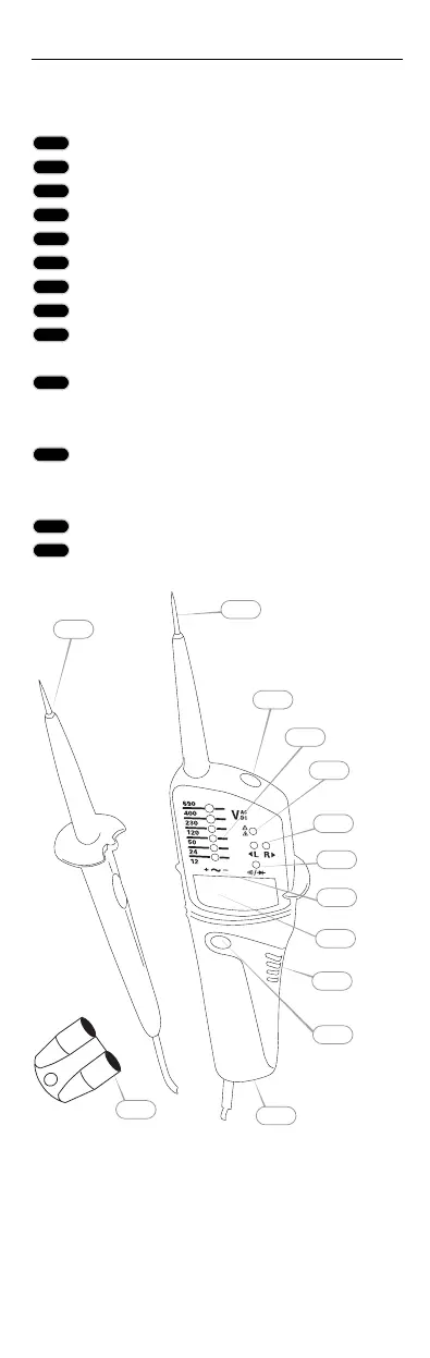
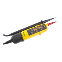
Control Elements and
Connections
Handle test probe - (L1)
Instrument test probe + (L2)
Measurement point illumination
LEDs for voltage display
LED for single-pole phase test
LED for left/right rotary field
LED for continuity
Polarity indication
LCD for voltage display (only FLUKE
T120 and T140)
Button on rear side - for measurement
point lightning (Also resistance measure-
ment and RCD Trip Test in T140VDE)
Accessible electrode for double-pole de-
termination of phase rotation and single-
pole phase test
Battery case
Test probe protection
1
3
4
2
5
6
7
8
9
10
11
12
13
13
12
11
10
9
8
7
6
5
4
3
2
1
Fluke T100/120/140
Control Elements
6
PFDB67410000.qxd 14.11.2006 9:26 Uhr Seite 6