FT25/35 Instruction Sheet 8/16/2004
English Page
2 of 6
Panel Size: 4-1/8" x 7"
Using the Visual Fault Locator
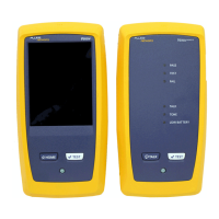
To use the VFL, refer to Figure 1 and do the following:
1 Remove the VFL’s dust cap; then clean the VFL’s output
adapter and the connector on the fiber to be tested.
2 Plug the fiber optic connector into the VFL’s output (
A).
The VFL’s universal fiber adapter accepts connectors with
2.5 mm ferrules (SC, ST, or FC). For 1.25 mm ferrules, use the
optional 1.25 mm universal adapter.
3 Press the
key (B) to turn on the VFL.
4 To toggle between continuous and flashing modes, press
the
FLASH key (C). The status LED (D) indicates the VFL’s
output status.
5 Turn off the VFL before disconnecting it from the fiber.
Replace the dust cap.
Tips: View the VFL’s light indirectly by holding a white card or
paper in front of the VFL output or the fiber connector
emitting the light.
The VFL’s light may not be visible through thick or dark-
colored cable sheaths or connector dust caps.
 Loading...