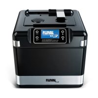
HYDRO TECH PERFORMANCE MONITOR
ADVANCED FILTRATION SYSTEM
www.fluval-g.com
EN.33
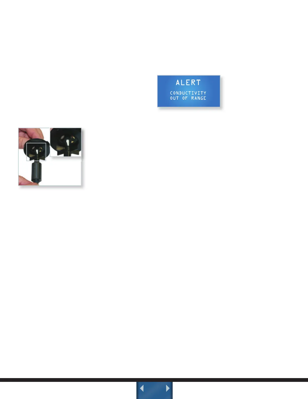
•Therearethreepartstotheimpeller:
-Ceramicimpellershaft+bottomrubber
bushings (glued together)
-Impellerassembly(Magnet+impellerblades)
- Top Rubber bushing which fits into the middle
circle of the impeller cover.
•Pullouttheceramicshaft.IMPORTANT: The
ceramic shaft is resistant to wear in use, but
is still fragile. Handle carefully during cleaning.
•Rinsetheimpellerassemblythoroughlywith
clean water.
•Ifnecessary,replacetheimpellerassemblyusing
original spare parts.
Put the ceramic shaft
back into the magnet.
Place the shaft back
into the centre part of
the cover, gently turning
and pressing the rubber
bushing until the ceramic
shaft is all the way into
the top rubber bushing.
•Re-inserttheimpellerassemblybackintothe
socket. You’ll feel it pull as the magnet is pulled
down into place. Align the impeller cover tabs
with the slots on the motor head and twist the
cover clockwise until it clicks back into place.
•Putthelterheadbackontothecanister,making
sure to fully press down. Align the lid on the
canister. Push down so that all four corners of
the lid are all the way down. If any of the corners
won’t go all the way down, check that all corner
fasteners are fully opened. Do not force.
•Whenthelidisproperlyaligned,closeallfour
metal lid fasteners.
•Replacethemechanicalpre-lterand
chemical cartridges back into place, making
sure to align them properly, and then turn the
knobs clockwise to lock cartridges into place.
Plug the filter back into the electrical socket.
NOTE: The FLUVAL G6 Upper Bushing consists of
a rubber element + a thrust bearing. Normally the
thrust bearing remains inside the rubber bushing,
but if it comes off or is removed, it must be
correctly re-installed before reassembling the unit.
The motor cannot operate without it. This applies
to the Fluval G6 model only.
PRIORITY #4 ALERT:
CONDUCTIVITY OUT OF
RANGE
POSSIBLE REASONS FOR AN EC ALERT:
1. There is not enough water in the filter. Check
that the filter cartridges and hoses are properly
installed, and the aquarium has enough water.
2. The filter has not been operating long enough.
The unit should run for 24 hours to release any
trapped air bubbles.
3. New gravel has been added triggering an “ion ex
change” activity. The solution would be to conduct
a simple water test, looking for General
Hardness (GH) and KH levels.
4. There is an increase in bacteria due to a build
up of waste. For example, the continuous
production of nitrifying bacteria caused by
continuous nitrate production can trigger an EC
warning. A proper test kit can determine if
Nitrate level is the problem.
5. Fertilizer, organic and inorganic pollutants or
other chemicals have been added to the water,
increasing the EC value. This can be corrected by
using a chemical analysis test kit.
Read more about Electrical Conductivity in the
Electrical Conductivity (EC) Monitoring System
Section.