操作使用说明
1. 将所配的3PIN插头,一端插入速度采集模块的“OUT”位置,另一端插入接收 机的 “IN”位置或
接另外的感应器的“IN”位置,如图12.6所示;
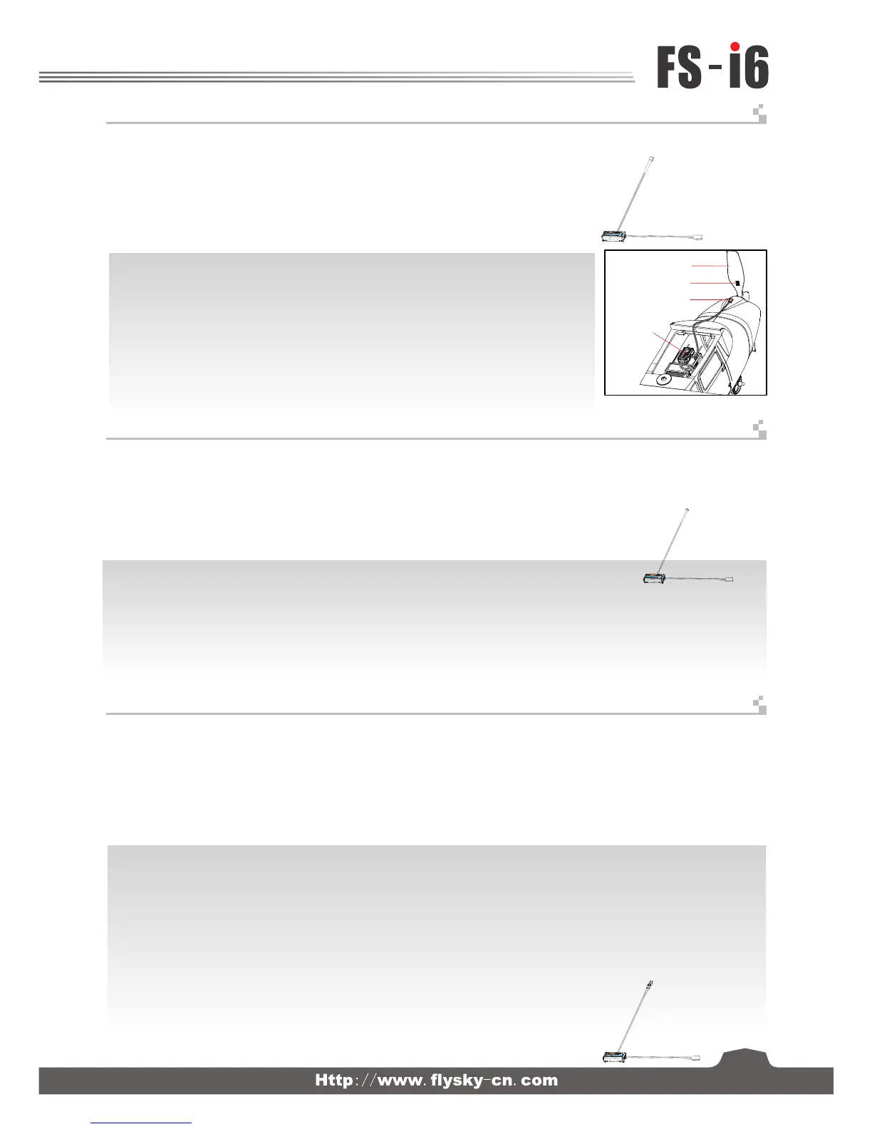
2. 如图12.7所示,将传感器与反射贴纸固定在测试的轴向转动,如安装在飞机的螺旋桨上,保持贴纸
平整,并与传感器垂直,传感器和贴纸距离要保持适中。
3. 打开发射机,接收机电源,在显示屏的接收机窗口内,会发现并显示“Motor speed 2:0RPM”,
试着转动,转速的值会发生变化,则表示安装成功。
操作使用说明:
1. 将所配的3 PIN连接线,一端插入温度采集模块的“OUT”位置,另一端插入接收机的“IN”位置或接另外的感应器的“IN”位置,
如图12.8所示;
2. 将温度的传感器本体,使用海棉双面贴粘在适当的位置(如:马达,电池本体上),并与被测试物表面紧贴;
3. 打开发射机,接收机电源,在显示屏的接收机窗口内,会发现并显示“Temperature 1:25.0℃”,表示安装成功,
25.0℃ 即为采集到的温度数据。
螺旋桨 Propeller
速度采集模块
Optical rotation
speed telemetry
module
9.07 FS-CTM01 温度采集模块连接 Temperature telemetry module connection setup
LED
FS-SPD02
SPEED
2
OUT
IN
Magnetic
9. 06 FS-CPD02 光感应转速采集模块 RPM Telemetry (optical) module setup
反射区 Magnet
传感器 Sensor
9. 08 FS-CVT01 电压采集模块连接
操作使用说明:
1. 将所配的3 PIN连接线,一端插入电压采集模块的“OUT”位置,另一端插入接收机的“IN”位置或接另外的感应器 的“IN”位置,如图12.9所示;
2. 打开发射机,接收机电源,在显示屏的接收机窗口内,会发现并显示“Ext.voltage4:0V”,表示安装成功;
3. 将用于检测的红黑线插针分别插入电池的插头内,红色线为正极,黑色线为负极,如图12.9所示:在显示屏的接收机窗口内,显示“Ext.voltage4:
12.40V",表示己检测到外部的电池电压为:12.40V。
注意:CVT01检测电压更宽,且无需担心反接烧坏,也可测本机电池电压。
(Pic 12.6)
(Pic 12.7)
(Pic 12.8)
(Pic 12.9)
1. Insert one end of standard 3 PIN plug into “OUT” port of temperature module, and insert the other end into “IN” port of
receiver or other sensor, as shown in the picture 12.8 .
2. Adhere temperature sensor to proper place (such as motor and battery) tightly by sponge double stick.
3. Switch on transmitter and receiver. “Temperature 1:25.0℃” will be shown in receiver window in display screen, which means
installation is successful, and 25.0℃ is the temperature collected.
1. Insert one end of standard 3 PIN plug into “OUT” port of external voltage module, and insert the other end into “IN” port
of receiver or other sensor, as shown in the picture 12.9.
2. Switch on transmitter and receiver. “Ext.voltage4:12.40V” will be shown in receiver window in display screen, which
means the installation is successful.
3. Insert red and black contact pin into battery port respectively. The red one is positive pole and the black one is
negative pole.as shown in the picture 12.9“Ext.voltage4:12.40V” is shown in the receive widow in display screen,
which means the tested voltage is 12.40V.
Notice: CVT01 detection voltage is wider, and no need to worry about reverse burn receiver,
also can measure the battery voltage..
1. Connect one end of the standard 3 PIN plug to the "out" port of the speed telemetry module
and the other end to the "in" port of the receiver or the previous sensors “in” port as shown in
the picture 12.6.
2. As shown in the picture 12.7: Affix the sensor and the reflection decals on the flat surface of
the side of any rotating part. Keep decals flat and perpendicular to the sensor. Maintain
sufficient safety distance between the sensor and the decals to avoid any damage.
3. Switch on the transmitter and the receiver. “Motor speed 2: 0RPM” will be displayed in the
main screen. The speed displayed will follow the speed of the rotating part monitored by the
rotation speed sensor, indicating a successful installation.
功能说明
此功能是为了能检测到模型的转速而做的,用户可通过遥控器来观察和监测模型的转速,当用户需要监测转速时,可使用此配件。
功能说明:
此功能是为了监测模型重要部件(马达,电池,调速器)温度而做的,用户可通过遥控器来观察和监测重要部件的温度,必要时可设定报警。
当用户需要检测重要部件温度时可使用此配件。
功能说明:
此功能是为了监测模型电池电压的,用户可通过遥控器来观察和检测电池的电压情况,必要时可进行设定报警。用户需要观察和监测电池电
压时可使用此配件。
This function allows the user to monitor turning speed via the transmitter. This is a very
useful function when determination of turning speed is required
This function allows the user to monitor the temperature of important operating parts of the system.
This will ensure that the user can be aware of any severe temperature changes which would adversely affect
system operation. The system will automatically set an alarm if the temperature is outside of safe operating norms
This function allows the user to monitor the battery voltage of the system. This will ensure that the user can beaware of
any severe voltage changes which would adversely affect battery operation. The system will automat-ically set an alarm if
the voltage is outside of safe operating norms
Function Details:
Operation instruction:
Function Details:
Operation instruction:
Function Details:
Operation instruction:
External voltage telemetry module connection setup
Digitalproportionalradiocontrolsystem
16
 Loading...