3. Run the cables up to the electrical panel or junction box, and connect them according to the
instructions in Connect the cables (page 50).
4. Place the pump on the base and make sure it cannot fall over or sink.
Alternatively, the pump can be suspended by its lifting eye just above the sump bottom.
5. Secure the cables.
Make sure that the cables cannot be sucked into the inlet of the pump. Support straps are required for
deep installations.
6. Secure the discharge hose or pipe in a safe manner.
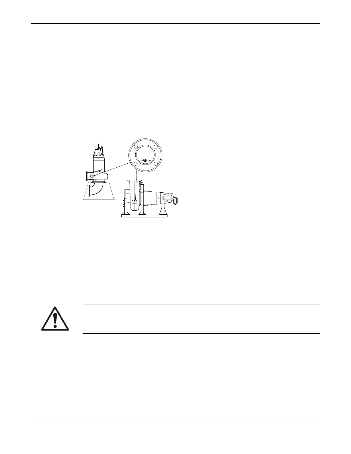
Install with T/Z-installation
• In the T-installation the pump is installed in a stationary vertical position in a dry well next to the wet
sump.
• In the Z-installation, the pump is installed in a horizontal position on a support stand, and a bell-
mouth is connected to the inlet pipe.
DANGER
DO NOT
OPEN BEFORE
DEENERGIZED
Figure 14: T-installation (left) and Z-installation
Z-installations using integrated cooling require a specific orientation. The drive unit must be oriented such
that the air evacuation system and the stator housing leakage sensor function properly. The cooling jacket
inspection cover marked “SENSORS” must be oriented downwards.
The following items are required:
• Support stand for anchoring the pump to a base
• Plate or base stand with anchor bolts for anchoring the pump to a concrete base
• Inlet elbow for connecting the suction line and discharge line
• Shut-off valves to permit the pump to be removed for service
• Air vent on the discharge side between the pump and the check valve
WARNING:
Never remove the inspection cover during service or internal cleaning of the pump housing until the pump
has been de-energized and drained.
1. For Z-installations: Check that the drive unit is oriented such that the cooling jacket inspection cover
marked “SENSORS” is facing downwards.
2. Fasten the pump:
a) Use the anchor bolts to bolt the base stand to the concrete base.
b) Bolt the pump to the base stand and the suction connection.
3. Make sure that the pump is vertical (T-installation) or horizontal (Z-installation).
4. Connect the suction line and discharge line.
5. Run the cables up to the electrical panel or junction box, and connect them according to the separate
instructions. For information about electrical connections, see Connect the cables (page 50).
6. Make sure that the weight of the pump does not put strain on the piping.
Installation
48 C3300/6x5, C/R3231, C3240, C3306, C3312, C3351, C3356, C3400, C3501, C3531, C3602, C3800 Installation,
Operation and Maintenance Manual