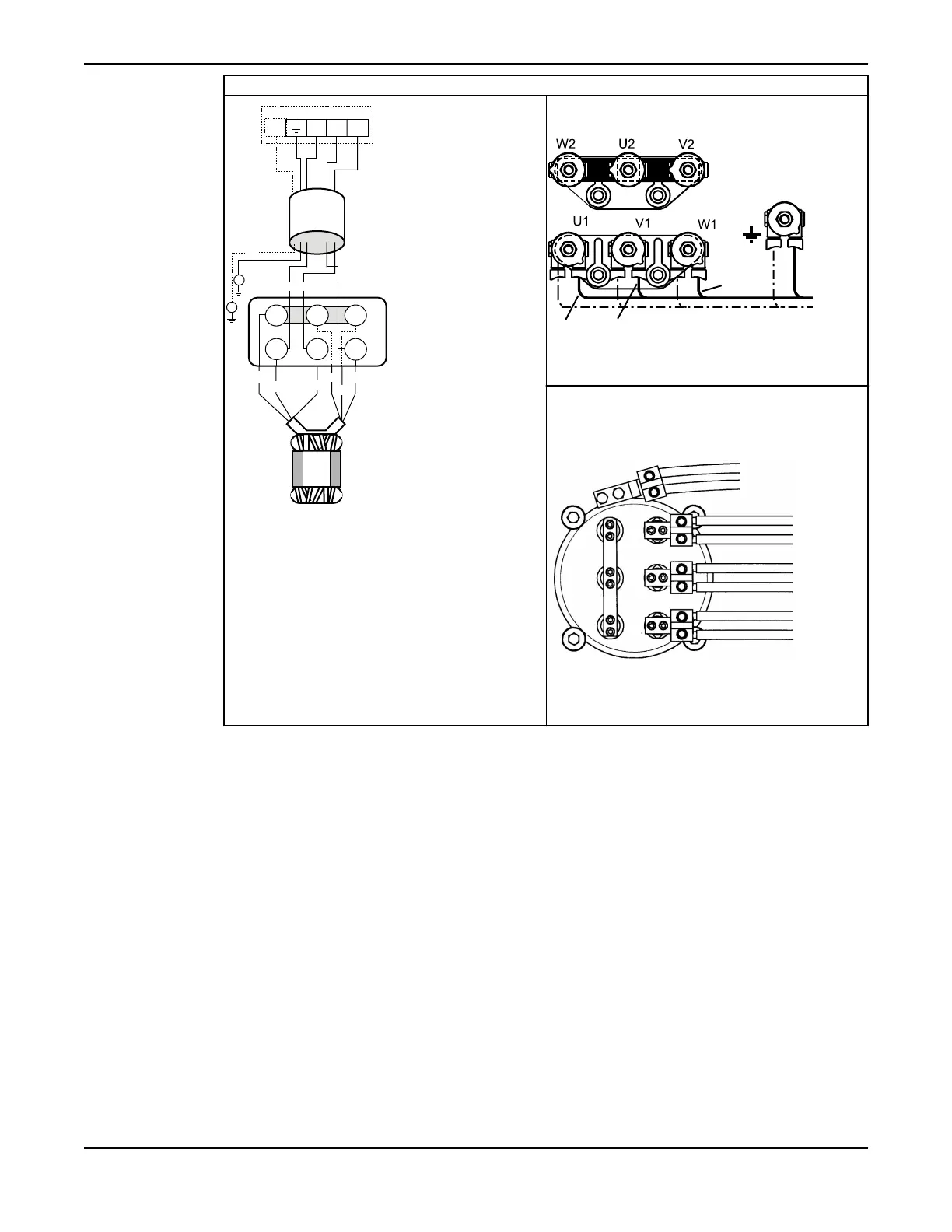
Y-connection, 1 or 2 cables
SUBCAB
GC
GC
L2 L3L1
GC
3~
V2
W1
W2
V2
U2
W2
U1
V1
V1 W1U1
U2
L2L3L1
Figure 33: Schematic diagram
This cable chart shows the connection for drive
units in the 6X5 and 7X5 series.
Figure 34: Drive units 605/615, 665/675;
705/715, 735/745, 765/775
This cable chart shows the connection for drive
units in the 8X5 and 9X5 series; also drive units 7X5
with large junction box (see Connection houses (junction
boxes) in 7X5 drive units (page 66)).
Figure 35: Drive units 805/815, 835/845,
865/875, 885/895; 905/915, 935/945, 965/975;
7X5 with large junction box
Installation
C3300/6x5, C/R3231, C3240, C3306, C3312, C3351, C3356, C3400, C3501, C3531, C3602, C3800 Installation,
Operation and Maintenance Manual
63