(TakeO is the point taken when the Flight Starts). Small course corrections are sometimes required and
these are shown on the GPS by a
ne adjustment indicator
in the form of a small arrow 4. Arrow 4 to the
left means the pilot should turn slightly to the left, and inversely arrow 4 to the right indicates a small
adjustment to the right is needed.
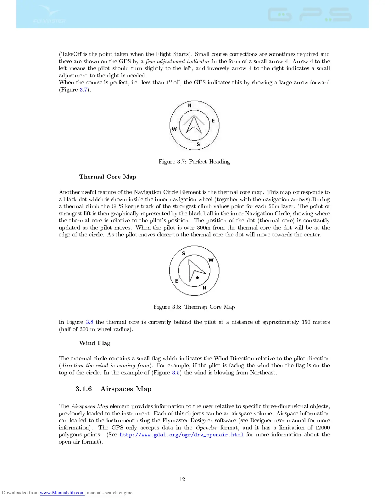
When the course is perfect, i.e. less than 1
º
o, the GPS indicates this by showing a large arrow forward
(Figure 3.7).
Figure 3.7: Perfect Heading
Thermal Core Map
Another useful feature of the Navigation Circle Element is the thermal core map. This map corresponds to
a black dot which is shown inside the inner navigation wheel (together with the navigation arrows).During
a thermal climb the GPS keeps track of the strongest climb values point for each 50m layer. The point of
strongest lift is then graphically represented by the black ball in the inner Navigation Circle, showing where
the thermal core is relative to the pilot's position. The position of the dot (thermal core) is constantly
updated as the pilot moves. When the pilot is over 300m from the thermal core the dot will be at the
edge of the circle. As the pilot moves closer to the thermal core the dot will move towards the center.
Figure 3.8: Thermap Core Map
In Figure 3.8 the thermal core is currently behind the pilot at a distance of approximately 150 meters
(half of 300 m wheel radius).
Wind Flag
The external circle contains a small ag which indicates the Wind Direction relative to the pilot direction
(
direction the wind is coming from
). For example, if the pilot is facing the wind then the ag is on the
top of the circle. In the example of (Figure 3.5) the wind is blowing from Northeast.
3.1.6 Airspaces Map
The
Airspaces Map
element provides information to the user relative to specic three-dimensional objects,
previously loaded to the instrument. Each of this objects can be an airspace volume. Airspace information
can loaded to the instrument using the Flymaster Designer software (see Designer user manual for more
information). The GPS only accepts data in the
OpenAir
format, and it has a limitation of 12000
polygons points. (See
http://www.gdal.org/ogr/drv_openair.html
for more information about the
open air format).
12