Figure 3.14: Wind Arrow
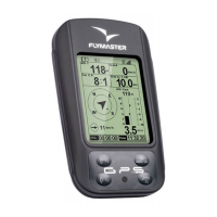
Note that both wind direction, and speed, are calculated based on the GPS ground speed while the pilot
is turning, so there is no need of wind speed probe. The wind speed calculation accuracy increases with
the number of turns made.
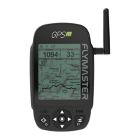
3.1.9 Map Page
The MAP element (Figure 3.15) provides information to the user about their position relative to waypoints,
cylinder edges and the pilot's trace or track. This element can be resized and moved around the screen.
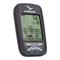
Figure 3.15: Map Element
A typical map page in ight may look like Figure. 20. In this gure is shown the scale on the bottom left.
The scale can be manually changed by pressing the F1 button to enlarge the map and therefore reduce
the scale, and conversely by pressing the F2 button to reduce the map and therefore increase the scale.
Figure 3.16: Map Page
If ying a competition route, the optimized route is drawn between the turnpoint cylinders. The position
of the pilot is indicated by the arrow and the trace for the last approximately 4 mins of the ight is shown.
Traces older than 4 mins are erased to reduce clutter on the screen.
15