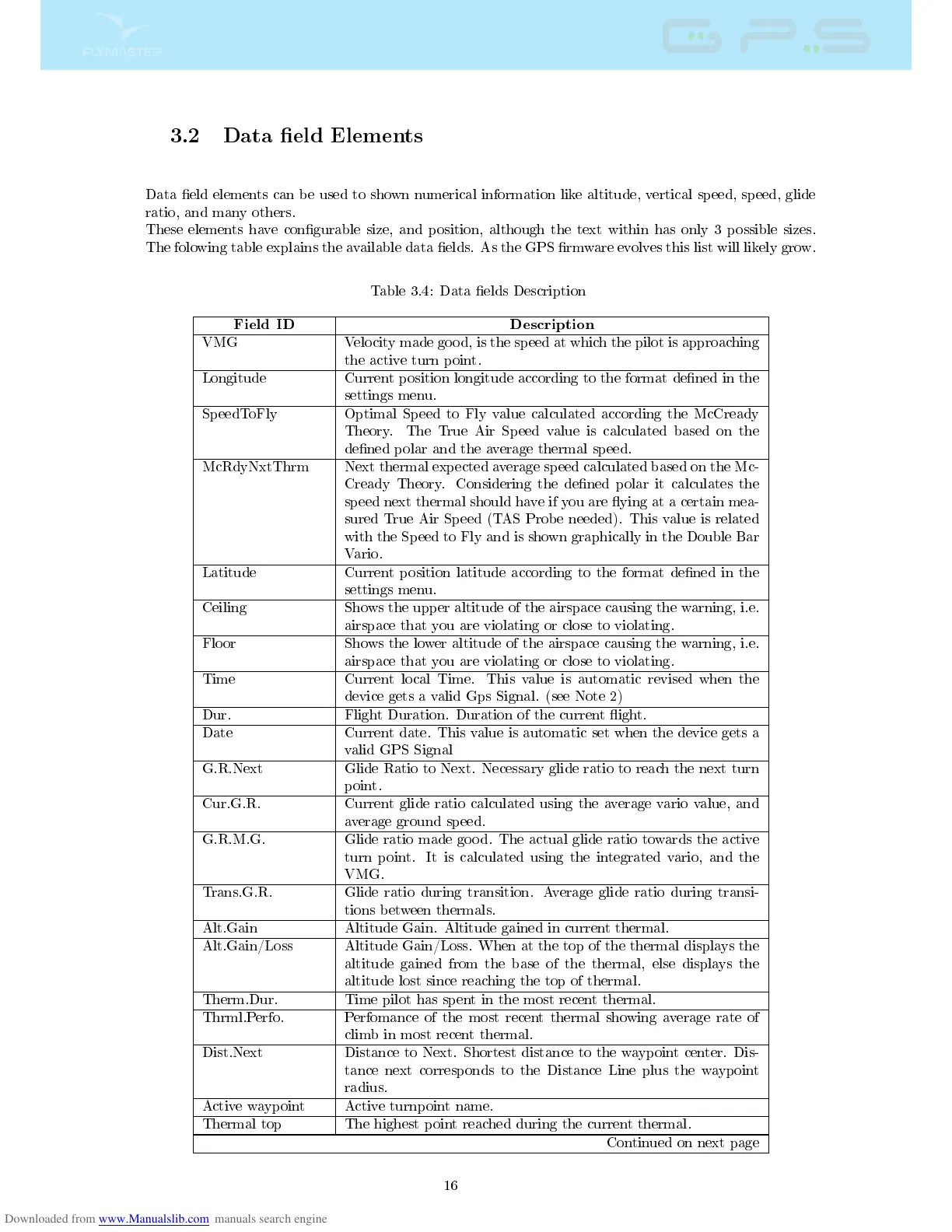
3.2 Data eld Elements
Data eld elements can be used to shown numerical information like altitude, vertical speed, speed, glide
ratio, and many others.
These elements have congurable size, and position, although the text within has only 3 possible sizes.
The folowing table explains the available data elds. As the GPS rmware evolves this list will likely grow.
Table 3.4: Data elds Description
Field ID Description
VMG Velocity made good, is the speed at which the pilot is approaching
the active turn point.
Longitude Current position longitude according to the format dened in the
settings menu.
SpeedToFly Optimal Speed to Fly value calculated according the McCready
Theory. The True Air Speed value is calculated based on the
dened polar and the average thermal speed.
McRdyNxtThrm Next thermal expected average speed calculated based on the Mc-
Cready Theory. Considering the dened polar it calculates the
speed next thermal should have if you are ying at a certain mea-
sured True Air Speed (TAS Probe needed). This value is related
with the Speed to Fly and is shown graphically in the Double Bar
Vario.
Latitude Current position latitude according to the format dened in the
settings menu.
Ceiling Shows the upper altitude of the airspace causing the warning, i.e.
airspace that you are violating or close to violating.
Floor Shows the lower altitude of the airspace causing the warning, i.e.
airspace that you are violating or close to violating.
Time Current local Time. This value is automatic revised when the
device gets a valid Gps Signal. (see Note 2)
Dur. Flight Duration. Duration of the current ight.
Date Current date. This value is automatic set when the device gets a
valid GPS Signal
G.R.Next Glide Ratio to Next. Necessary glide ratio to reach the next turn
point.
Cur.G.R. Current glide ratio calculated using the average vario value, and
average ground speed.
G.R.M.G. Glide ratio made good. The actual glide ratio towards the active
turn point. It is calculated using the integrated vario, and the
VMG.
Trans.G.R. Glide ratio during transition. Average glide ratio during transi-
tions between thermals.
Alt.Gain Altitude Gain. Altitude gained in current thermal.
Alt.Gain/Loss Altitude Gain/Loss. When at the top of the thermal displays the
altitude gained from the base of the thermal, else displays the
altitude lost since reaching the top of thermal.
Therm.Dur. Time pilot has spent in the most recent thermal.
Thrml.Perfo. Perfomance of the most recent thermal showing average rate of
climb in most recent thermal.
Dist.Next Distance to Next. Shortest distance to the waypoint center. Dis-
tance next corresponds to the Distance Line plus the waypoint
radius.
Active waypoint Active turnpoint name.
Thermal top The highest point reached during the current thermal.
Continued on next page
16