www.fmiproducts.com
124387-01D10
PRE-INSTALLATION PREPARATION
Continued
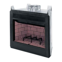
WARNING: When nishing
appliance,donotoverlapcom-
bustiblematerialontotheblack
front face. Brick, tile or other
noncombustiblematerialsmay
beappliedtothefaceprovided
thatanygapisbetweenthemate-
rialusedandthefaceiscaulked
withanoncombustiblecaulking.
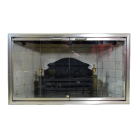
3" (7.6 cm)
1
1
/
2
"
(3.8 cm) Max.
8"
6" (15.2 cm)
14"
12"
(22.9 cm)
Combustible
Materials
30°
Figure 9 - Mantel Clearances - Side View
(Cross Section)
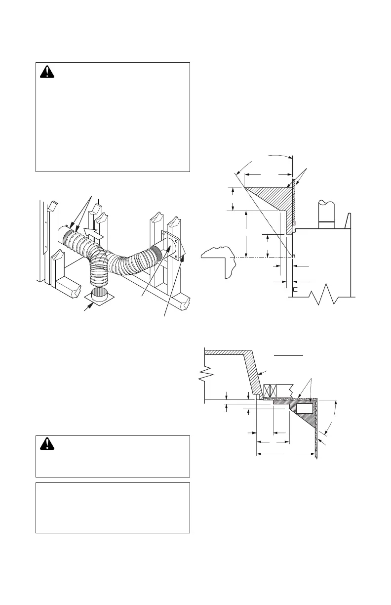
Figure 8 - Outside Air Kit
Secure to Collars with Metal Tape, Screws
or Straps (Min. of 1/4" x 20" in size)
Air Inlet
Location
Must Allow
For Bushes
or Snow
Vent Hood
Required for
Wall Installation
Air Inlet
Eyebrow
Vented Crawl Space
(Check Local Codes
Before Installing in a
Vented Crawl Space)
OPTIONAL OUTSIDE AIR KIT
(MODEL AK4/AK4F)
Installation of an outside air kit should be
performed during rough framing of replace
due to the nature of it's location. Outside com-
bustion air is accessed through a vented crawl
space (AK4F) or through a sidewall (AK4).
CAUTION: Combustion air
inlet ducts shall not terminate
in attic space.
The maximum height for the
air vent can not exceed 3 feet
belowtheuegasoutletofthe
termination.
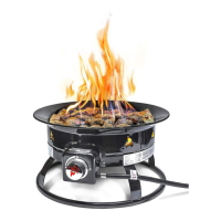
1
1
/
2
"
(3.8 cm)
Max.
3" (7.6 cm)
Max.
6" (15.2 cm)
Max.
9"
(22.9 cm)
12"
(30.5 cm)
Outer
Surround
Combustible
Material May
Be Used
TOP VIEW
SAFE
ZONE
Perpendicular
Wall
33°
Figure 10 - Side Clearances - Top View
(Cross Section)
MANTELS
A combustible mantle shelf maybe installed
a maximum 12" (22.9 cm) from the wall.
Figures 9 and 10 show the minimum al-
lowable distances from various combus-
tible mantle components in relation to the
fireplace opening.