www.fmiproducts.com
124387-01D 27
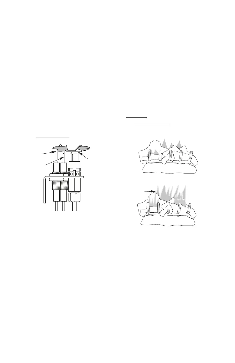
INSPECTING BURNERS
Pilot
Burner
Figure 44 - Correct Pilot Flame Pattern
Check pilot ame pattern and burner ame
patterns often.
PILOT ASSEMBLY
The pilot assembly is factory preset for the
proper ame. Alterations may have occurred
during shipping and handling. The pilot is
located on right hand side of burner.
The ame must envelope 1/4" of top of the
ignitor/sensor and grounding stem.
If your pilot assembly does not meet these
requirements:
• Turn the adjustment screw marked PILOT
clockwise to decrease or counterclockwise
to increase the ame to proper size (see
Figure 44). Do not remove the adjustment
screw.
• see Troubleshooting, page 30
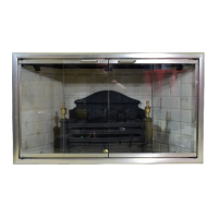
BURNER FLAME PATTERN
Burner ames will be steady, not lifting or oat-
ing. Flame patterns will be different from unit
to unit and will vary depending on installation
type and weather conditions.
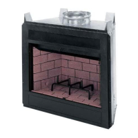
If the vent conguration is installed incorrectly,
ames will lift or "ghost". This can be danger-
ous. Inspect ames after installation to ensure
proper installation and performance.
Figure 45 shows a typical ame pattern.
If burner ame pattern differs from that de-
scribed:
• turn replace off (see To Turn Off Gas to
Appliance, page 25)
• see Troubleshooting, page 30
Figure 45 - Correct Burner Flame Pattern
Figure 46 - Incorrect Burner Flame
Pattern
Yellow
Tipping