www.fmiproducts.com
124387-01D 5
INTRODUCTION
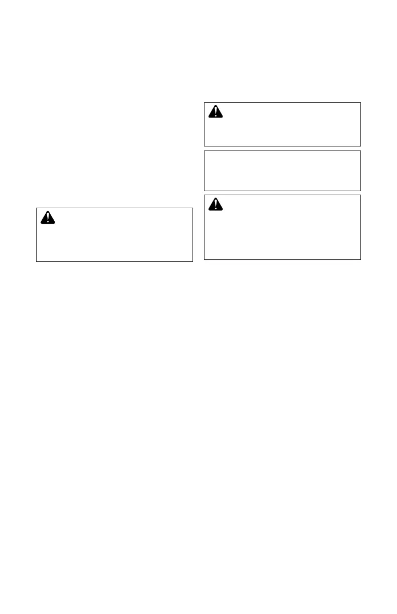
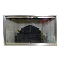
Models BBM-36(N,P)-JHB, BBM-42(N,P)-
JHB and BBM-50(N,P)-JHB are log/gas
burner modules that use an electronic control
valve and ignition system. These modules are
installed into replace chassis models BVC-
36YA, BVC-42YA and BVC-50YA along with
the Mosaic Masonry™ engineered rebrick
wall models MKB-36(H,S)-(I,R)A, MKB-
42(H,S)-(I,R)A and MKB-50(H,S)-(I,R)A. A
FMI PRODUCTS, LLC venting system and
vent cap are not supplied, but are required for
proper operation. If a B-type venting system
is installed, transition pipe model BTC-8 is
required. See venting instructions beginning
on page 11.
WARNING: This gas appli-
ancemustnotbeconnectedto
achimneyueservicingasolid
fuelburningappliance.
BEFORE YOU BEGIN
Before beginning the installation of your re-
place chassis, rebrick walls or module, read
these instructions through completely.
This FMI PRODUCTS, LLC appliance and
its approved components are safe when
installed according to this installation manual
and are operated as recommended by FMI
PRODUCTS, LLC. Unless you use FMI
PRODUCTS, LLC approved components
tested for this appliance, YOU MAY CAUSE
AFIREHAZARD!
The FMI PRODUCTS, LLC warranty will
be voided by and FMI PRODUCTS, LLC
disclaims any responsibility for the following
actions:
A) Modication of the appliance or any of the
components.
B) Use of any component part not approved
by FMI PRODUCTS, LLC in combination
with this appliance.
C) Installation and/or operation in a manner
other than instructed in this manual.
D) The burning of anything other than the
type of gas approved for use in this gas
appliance.
The installation must conform with local
codes or, in the absence of local codes, with
the current National Fuel Gas Code, ANSI
Z223.1/NFPA 54.
WARNING: Installation of this
appliance should be done by a
qualiedserviceperson.
NOTICE: This appliance is not
intendedtobeusedasaprimary
source of heat.
CAUTION: Do not connect
appliancebeforepressuretest-
inggaspiping.Damagetogas
valvemayresultandanunsafe
conditionmaybecaused.
The appliance and it’s individual shutoff valve
must be disconnected from the gas supply
piping system during any pressure testing of
that system at test pressures in excess of 1/2
psig (3.5 kPa).
The appliance must be isolated from the gas
supply piping system by closing its individual
manual shutoff valve during any pressure
testing of the gas supply piping system at
test pressures equal to or less than 1/2 psig
(3.5 kPa).
For the purpose of input adjustment two
pressure taps (for IN and OUT pressures)
are provided on the gas control valve for test
gauge connections to the appliance.