www.fmiproducts.com
124387-01D 15
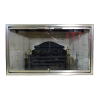
Terminations/SparkArrestor
Fireplace system must be terminated with
listed round top or chase terminations. In any
case, refer to installation instructions supplied
with termination. Terminations approved for
this replace are RT-8DM, RTL-8DM and
RLT-8DM that can be used for ashing or
chase and ET-8DM, ETO-8DM, ETL-8DM
and ETLO-8DM for chase style termination
only. Figure 19 shows an RTL-8DM round
top termination.
CAUTION: Do not seal open-
ingsontherooftopashing.Fol-
lowtheinstallationinstructions
provided with the termination
beingused.
Terminations with 16" slip pipe sections are
available. RTT-8DM, RTTL-8DM and RLTT-
8DM are approved for ashing installations.
When needed, these adjustable terminations
may be used in combination with pipe assem-
bly to achieve correct chimney height.
Note: In rare instance there is a problem with
side driven rain or wind or chimney is not
drafting properly, an ADS-8DM (Anti-Draft
Shield) can be used with round terminations.
VENTING INSTALLATION
Continued
Attach Bracket
Tabs to
Outer Pipe
(3 Places)
Secure with
Screws
RTL-8DM
Level of
Flue Gas
Outlet
Caulk
Collar
Flashing
Underlap Shingles
Bottom Only
Figure 19 - Termination
Overlap
Shingles Top
and Sides
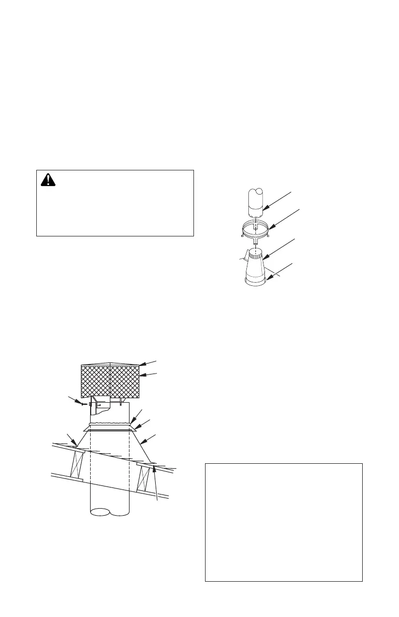
VENTING INSTALLATION USING 8"
B-TYPE VENTING SYSTEM
Transition pipe model BTC-8 and starter collar
are shown in Figure 20. Remove starter collar
and set aside. Slide transition pipe over vent
collar and attach with a minimum of 4 screws.
Replace starter collar over transition pipe and
attach using 4 screws located on leg stands.
To install b-vent piping, slide rst piece of
b-vent over transition pipe and attach with
either a minimum of 3 screws or other means
approved by the vent manufacturer.
B-Vent Piping
Transition Pipe
Model BTC-8
Starter Collar
Vent Collar
Figure 20 - Installing Transition Pipe and
Starter Collar
CHECKING FOR PROPER VENTING
After completing and checking electrical, gas
and vent connections, follow the lighting in-
structions and allow the main burner to run for
approximately 5 minutes. Hold a lighted match
near the top edge of replace opening and play
it along entire length of opening (see Figure 21,
page 16). Proper venting should tend to draw
the ame or smoke into the appliance. Improper
venting or escaping of spillage of burned gas, is
indicated when the match ickers or goes out.
If the appliance is found to be improperly
venting, shut it off and notify your installer
or a qualied service agency to inspect the
venting system.
NOTICE: This appliance is
equipped with a vent safety
shutoff switch which will shut
downtheapplianceinthecaseof
aventingproblem.Donotbypass
theventsafetyswitch.Iftheappli-
anceshouldshutdown,contacta
qualiedinstaller,serviceagency
or your gas supplier to have the
ventinspectedbeforeoperating.