12
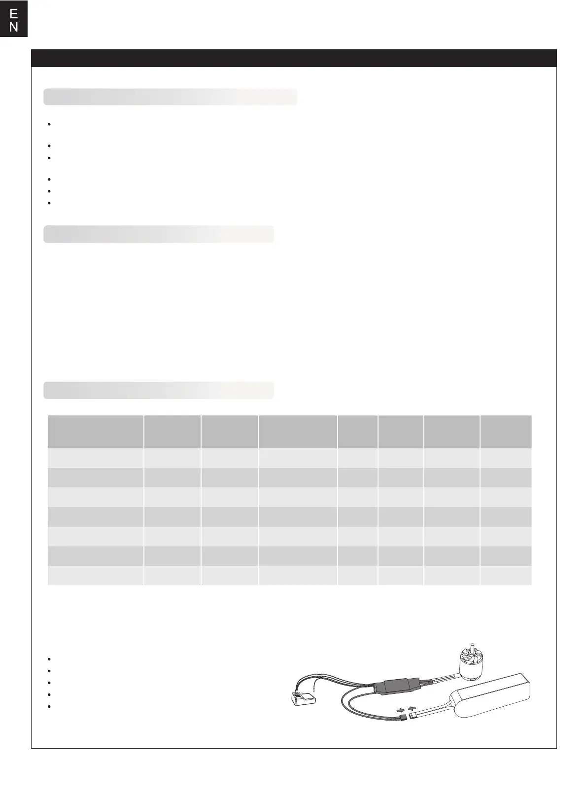
Wires Connection:
Specification
Key features
1. Utilizes powerful next generation MOSFET with a low thermal signature, high peak current threshold and reliability.
2. Features high performance 32bit microprocessor as standard. Stronger computing ability and faster processing rates.
3. Super smooth start up and throttle throughout the power range.
4. Higher driving efficiency and more energy-saving.
5. Adjustable SBEC output voltage, 5V/6V. (40A/50A/60A/80A/100A have SBEC adjustable)
6. Multiple protection protocols: start-up, over-heat, low-voltage cutoff, signal loss, phase loss etc.
7. Supports wide range of high RPM type motors commonly found in today's market.
8. Fully programmable via optional ZTW mobile app or ZTW LCD programming card.
The speed controller can be connected to the motor by soldering directly or with high quality connectors. Always use new
connectors, which should be soldered carefully to the cables and insulated with heat shrink tube. The maximum length of the
battery pack wires shall be within 6 inches.
Brushless ESC Introduction
ZTW is not responsible for your use of this product, or any damage or injuries you may cause or sustain as a result of its
usage.
Always place safety as priority when you use the product.
An electric motor that is connected in combination with a battery and/or ESC may start unexpectedly and cause serious
damage and so should always be used with care and respect.
We recommend you always remove the propeller when working on a model with the power source connected.
Follow and observe all local laws and by-laws relating to model flying when flying RC planes.
Never fly over others or near crowds.
Solder controller to the motor wires.
Solder appropriate connectors to the battery wires.
Insulate all solder connectors with heat shrink tubes.
Plug the “JR” connector into the receiver throttle channel.
Controller Red and Black wires connects to battery pack
Red and Black wires respectively.
ESC
Motor
Battery
Throttle Signal Wire
Reverse
Signal
Wire
Receiver
Beatles 20A SBEC G2 3020211 20A/30A
30A/40A
40A/55A
50A/65A
6OA/80A
80A/100A
3030211
3040211
3050211
3060211
3080211
30100211
Type PN#Model
Cont./Burst
Current(A)
Size(mm)
L*W*H
User
Program
Battery cell
NiXX\Lipo
Weight
(g)
BEC
Output
Beatles 30A SBEC G2
Beatles 40A SBEC G2
Beatles 50A SBEC G2
Beatles 60A SBEC G2
Beatles 80A SBEC G2
Beatles 100A SBEC G2 100A/120A
5-12NC/2-4Lipo
5-12NC/2-4Lipo
5-12NC/2-4Lipo
5-12NC/2-4Lipo
5-18NC/2-6Lipo
5-18NC/2-6Lipo
5-18NC/2-6Lipo
25
25
37
37
50
75
80
5.5V/4A
5.5V/4A
5V/6V 4A
5V/6V 4A
5V/6V 8A
5V/6V 8A
5V/6V 8A
60*25*10
60*25*10
68*25*10
68*25*10
70*34*10
90*37*10
90*37*10
Yes
Yes
Yes
Yes
Yes
Yes
Yes
Important warnings