8
EN
Get your model ready to fly
Transmitter and model setup
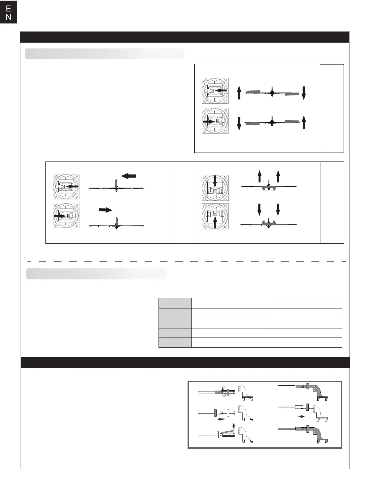
Aileron
Bank left
Bank right
Before getting started, bind your receiver with your transmitter.
Please refer to your transmitter manual for proper operation.
CAUTION: To prevent personal injury, DO NOT install the
propeller assembly onto the motor shaft while testing the control
surfaces. DO NOT arm the ESC and do not turn on the
transmitter until the Transmitter Manual instructs you to do so.
Tips: Make sure all control sticks on your radio are in the neutral
position (rudder, elevator, ailerons) and the throttle is in the OFF
position. Make sure both ailerons move up and down (travel) the
same amount. This model tracks well when the left and right
ailerons travel the same amount in response to the control stick.
Move the controls on the transmitter to make sure the aircraft
control surface moves correctly. See diagrams.
Elevator
Climb
Descend
Steering Rudder
Steer left
Steer right
High Rate Low Rate
Elevator
Aileron
Rudder
Flap
20mm up / dowm 16mm up / dowm
12mm up / dowm
20mm left / right
30mm up / donw
18mm up / dowm
24mm left / right
35mm up / down
Control throws
The suggested control throw setting for this airplane are as follows (dual rate setting):
Tips: On the first flight, fly the model in low rate.
The first time you use high rates,be sure to fly at
low to medium speeds. High rate, as listed, is
only for EXTREME maneuvering.
a.
b.
c.
d.
e.
f.
Clevis installation
1.Pull the tube from the clevis to the linkage.
2.Carefully spread the clevis, then insert the clevis pin into the
desired hole in the control horn.
3.Move the tube to hold the clevis on the control horn.