FITTING THE BURNER TRAY
Imoprtant NNote: CCheck tthe tthermocouple nnut cconnection iinto tthe rrear oof tthe vvalve iis ssecure.
Temporarily fit the burner tray and ensure a suitable gas route can be
achieved. Place the burner tray into the firebox making sure that the rear
lugs locate properly on to the ledge in the firebox. Fit the two securing
screws through the tray legs to secure the assembly.
Connect the gas supply and tighten the gas connections. Fit the data/con-
trol plate to the tray using the two screws provided. Ensure that the con-
trol knob can be pushed fully in and does not touch the plate.
Fit the deflector baffle to the two locations on the front face of the fire-
tray. Screws are provided for this purpose. The baffle should be level with
the lower edge of the tray. Place the front casting in front of the fire tem-
porarily to check the angle of the baffle. The casting should fit well and
the control devices beneath should not be visible to the eye. Realign the
baffle slightly if necessary to achieve the correct fit.
GAS CONNECTION
Purge the gas supply to remove any air, and connect the previously installed gas supply to the control tap and tighten all joints.
If using an across hearth connection ensure the decorative frame and firefront will clear the supply route. If the data/control palte is not
already fitted, attach with two screws, ensuring the control knob is free to
be depressed fully.
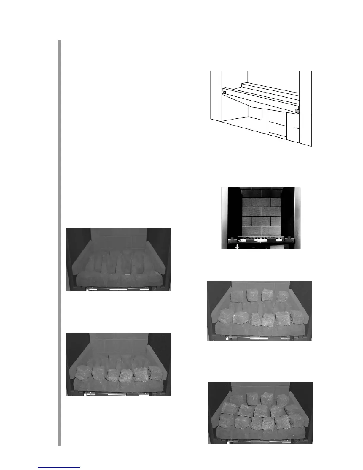
FUEL BED LAYOUT
Place the brick panel against the rear of the firebox
Place the ceramic combustion matrix onto the burner and the ceramic side
cheeks onto the matrix.
Place the front row of six coals on to the matrix, with the two coals sec-
ond front each end turned on their sides. Ensure the coals are firmly
against the side cheeks as shown in the photograph. If necessary, pull the
coals forward slightly to ensure their rear edges do not overhang the flame
ports. Corners or rough edges MUST NOT be allowed to enter the flame
ports. If in any doubt pull the coals as far forward as possible.
Place the rear row of four coals, making sure that the flat sides are firmly against
the brick panel and side cheeks as shown.
Place the middle row of five coals onto the flats in the matrix. Ensure the
coals are not put into the holes in the matrix. Place the two end coals firm-
ly against the side cheeks and back to the steps on the matrix, turning them
on to their sides as shown.
Note: TThe ccoals mmust nnot bbe ccrammed ttogether, oor iinserted iinto tthe hholes
in tthe mmatrix. AA wwell llaid oout, ggenerously sspaced ccoal llayout wwill ggive
the bbest rresults.
7
8.5
9.0
8.6