C
cheryl09Aug 8, 2025
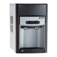
Why is my Follett 12CI425A-S Water Dispenser not dispensing water?
- RRachel WintersAug 9, 2025
If your Follett Water Dispenser isn't dispensing water, there are a few potential causes. It could be a faulty water solenoid valve, which would need to be replaced. Another possibility is a faulty dispense switch, which would also need replacement. Finally, ensure the power switch is on and functioning correctly; if it's faulty, replace it.