EasyManua.ls Logo

Follett 15CI100A Service Manual

Follett 15CI100A
36 pages
To Next Page IconTo Next Page
Page #1 background imageLoading...
Page #1 background image
Installation and Service Videos:
www.follettice.com/servicevideolibrary
01214261R01
801 Church Lane • Easton, PA 18040, USA
Toll free (877) 612-5086 • +1 (610) 252-7301
www.follettice.com
Installation, Operation and Service Manual
Serial numbers after K39468
Countertop and Freestanding Ice and Water
Dispenser with Chewblet
®
Ice Machine
Rear Drain Model
15CI100A
Welcome to Follett
Follett equipment enjoys a well-deserved reputation for excellent performance, long-term reliability and outstanding
after-the-sale support. To ensure that this equipment delivers that same degree of service, review this guide
carefully before you begin your installation.
Should you need technical help, please call our Technical Service group at (877) 612-5086 or (610) 252-7301.
Please have your model number, serial number and complete and detailed explanation of the problem when
contacting Technical Service.
Getting Started
After uncrating and removing all packing material, inspect the equipment for concealed shipping damage. All freight
is to be inspected upon delivery. If visible signs of damage exist, please refuse delivery or sign your delivery receipt
"damaged." Follett Customer Service must be notied within 48 hours. Wherever possible, please include detailed
photos of the damage with the original packaging so that we may start the freight claim process.
Question and Answer IconNeed help?

Do you have a question about the Follett 15CI100A and is the answer not in the manual?

Follett 15CI100A Specifications

General IconGeneral
BrandFollett
Model15CI100A
CategoryWater Dispenser
LanguageEnglish

Summary

Welcome and Getting Started

Initial Inspection and Damage Reporting

Procedures for inspecting new equipment and reporting any shipping damage within 48 hours.

Before You Begin Installation

Model Configuration Explanation

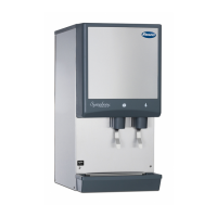
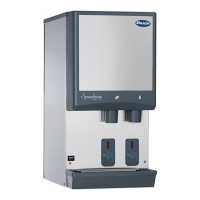
Understanding the Follett dispenser model number to verify the received unit.

Product Specifications

Dimensions, Ambient, and Plumbing

Key physical dimensions, environmental limits, and water supply requirements.

Detailed Specifications

Water, Clearances, Electrical, and Refrigeration

Water mineral content, installation clearances, electrical needs, and refrigerant details.

15 Series Dimensional Drawing

Countertop Model Dimensions

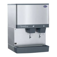
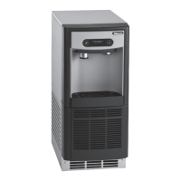
Visual representation of countertop model dimensions and connection points.

Installation Guide

Countertop Installation Procedure

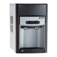
Step-by-step instructions for installing the countertop dispenser.

Optional Installation Kits

Leg and Water Filter Installation

Instructions for installing optional leg accessories and internal water filters.

Maintenance and Access

Maintenance and Cleaning Modes

How to engage Cleaning and Maintenance modes for operational control.

Accessing Internal Components

Steps to remove the front panel for accessing internal parts.

Filter Display and Reminders Configuration

Activating Filter Display Indicator

Configuring the filter display indicator using DIP switches for water filtration.

Disabling Maintenance Reminder

Method to disable the six-month maintenance/filter change reminder.

Cleaning and Sanitizing Procedure

SafeCLEAN Plus Application Steps

Detailed steps for applying cleaning solution, sanitizing the ice machine, and dispensing ice.

Cleaning Procedure Details

Rinsing and Exterior Cleaning

Procedures for rinsing the unit, cleaning the user interface, and exterior panels.

Service and LED Indicators

LED Indicator Status Meanings

Comprehensive guide to understanding the meaning of each LED indicator on the dispenser.

Evaporator Disassembly

Initial Component Removal

Steps for disconnecting power/water and removing the chute, drip tray, and front panel.

Evaporator Disassembly Continued

Gear Motor and Compression Nozzle Removal

Detailed instructions for removing the gear motor and compression nozzle components.

Evaporator Disassembly Final Steps

Main Housing Removal Procedure

Steps for disconnecting the vent line and removing the main housing from the evaporator.

Evaporator Assembly

Main Housing and Auger Installation

Guide for installing the main housing, O-ring seal, and the auger assembly.

Evaporator Assembly Reassembly

Compression Nozzle and Gear Motor Reinstallation

Instructions for reinstalling the compression nozzle, transport tube, and gear motor.

Evaporator Assembly Alignment

Auger Shaft and Retainer Installation

Steps for aligning the auger shaft and installing the spacer and retainer correctly.

Evaporator Assembly Wiring

Gear Motor Electrical Connections

Connecting the gear motor wires and ground wire as per the diagram.

Water Feed System Diagram

Water Supply Path Schematic

Schematic illustrating the water supply path, including optional filter and solenoid valve.

System Schematics Overview

Storage Bin and Vent Systems

Diagrams detailing the storage bin drain, melt water, and vent tube configurations.

Refrigeration System Diagram

Refrigeration Cycle Components

Visual representation of the refrigeration cycle, compressor, evaporator, and condenser.

Condenser Fan Motor Removal

Condenser Fan Motor Removal Guide

Illustrated guide for removing the condenser fan motor, noting it's shown for the 7 Series.

User Interface Operation

Interface Display Identification

Identification of user interface displays for normal operation and cleaning modes.

User Interface Service Displays

Service Display Interpretation

Identification of user interface displays indicating service conditions and errors.

Electrical Wiring Diagram

Dispenser Electrical Connections

Detailed schematic showing all electrical connections and component wiring for the dispenser.

Parts Identification - Exterior

Exterior Components Exploded View

Exploded view diagram showing exterior components of the 15 Series dispenser.

Exterior Parts List

Exterior Parts Reference Table

A table listing exterior parts with reference numbers and corresponding part numbers.

Parts Identification - Interior

Interior Components Exploded View

Exploded view diagram showing interior components of the 15 Series dispenser.

Interior Parts List

Interior Parts Reference Table

A table listing interior parts with reference numbers and corresponding part numbers.

Parts Identification - Bin Assembly

Bin Assembly Components Exploded View

Exploded view diagram showing components of the 15 Series bin assembly.

Bin Assembly Parts List

Bin Assembly Parts Reference Table

A table listing bin assembly parts with reference numbers and corresponding part numbers.

Parts Identification - Evaporator Assembly

Evaporator Components Exploded View

Exploded view diagram showing components of the evaporator assembly.

Evaporator Assembly and Miscellaneous Parts

Evaporator and Miscellaneous Parts List

Lists for evaporator assembly parts and miscellaneous items like filters and legs.

Warranty and Support Information

Warranty Registration and Evaluation

Details on warranty registration, product evaluation, and contact information for technical support.

Related product manuals