D
Deborah NelsonAug 8, 2025
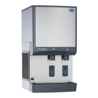
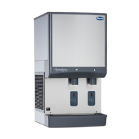
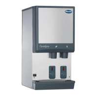
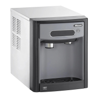
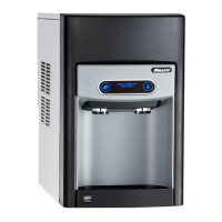
Why Follett 25CI400W Water Dispenser does not dispense ice?
- SStephanie NashAug 8, 2025
There are several possible causes: 1. The power switch might be off or faulty. Check the switch, turn it on, or replace it if it’s faulty. 2. The dispense switch might be faulty. If so, replace the switch. 3. The wheel motor might have a malfunction. Check the motor and capacitor, and replace them if needed.