
H
heatherharrisonAug 13, 2025
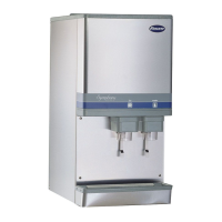
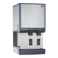
Why is my Follett Water Dispenser not dispensing water?
- DDesiree GrahamAug 13, 2025
If your Follett Water Dispenser is not dispensing water, there are several potential causes: 1. A faulty water solenoid valve may be the issue. Consider replacing it. 2. A faulty dispense switch could also be the reason. Replace the dispense switch. 3. The power switch might be off or faulty. Check the switch, turn it on, or replace it if necessary.