26 25CI400A/W • 25HI400A • 50CI400A/W • 50HI400A
Normal operation – Stage 5
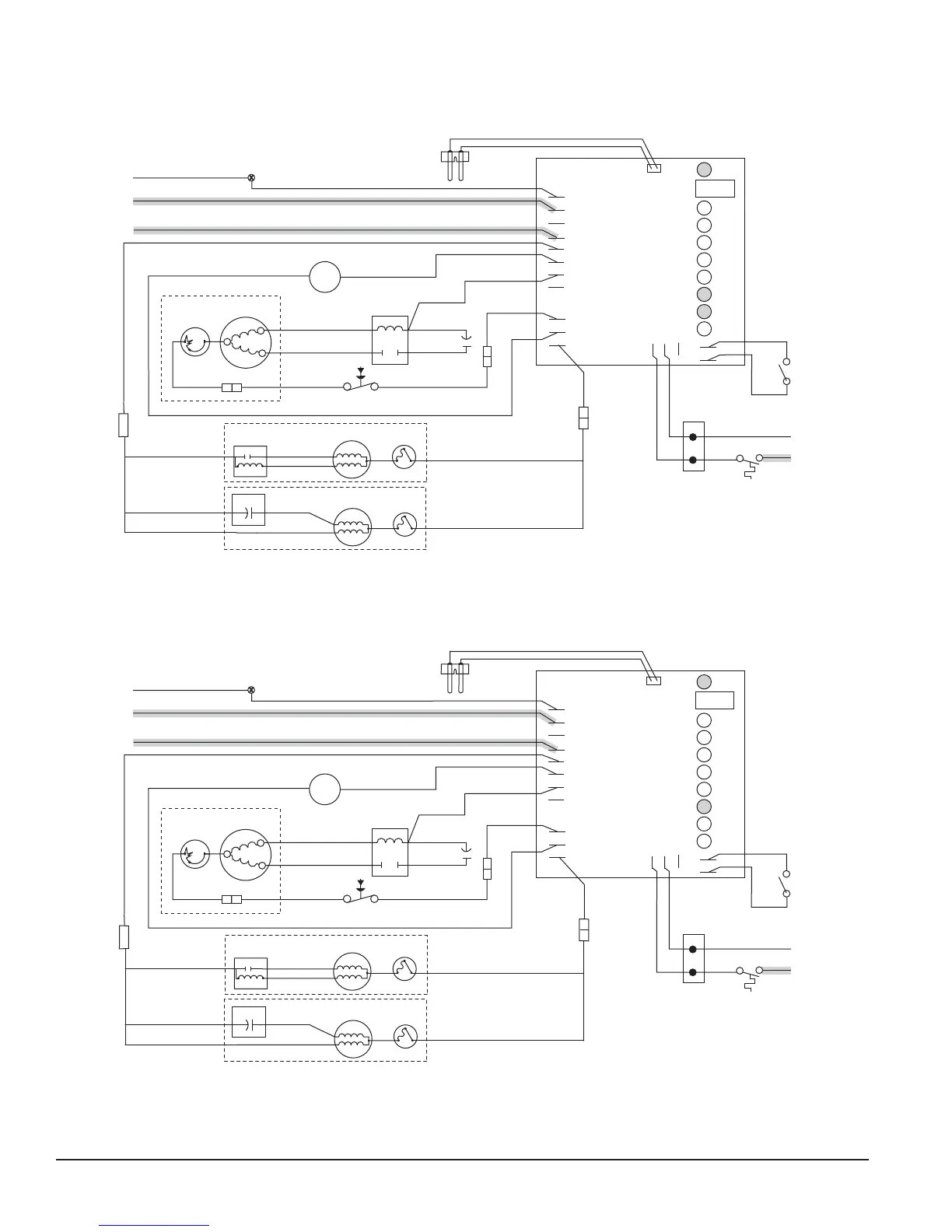
The drive motor now shuts down and the DR LED is off. The B-T LED remains on for 20 minutes. The ice machine will
not start while the B-T LED is on. To restart the ice machine for troubleshooting purposes, depress the reset button to
clear the control board.
GRD
L1
L1
L2
L2
L2
L2
L2
COMPRESSOR
FAN
DRIVE
DR
C
20M
60M
2ND
WTR
B-T
B-E
RESET
GRD
G
B
W
FAN
BLACK
WHITE
BLACK
BLACK
R
ORANGE
S
S
L
COMPRESSOR
C
RED
BLACK
BLACK
INPUT
POWER
WATER
SENSOR
CONTROL
BOARD
24V
COMMON
LINE VAC
RED
RED
WHITE
BLACK
BIN T-STAT
BIN SIGNAL
FROM DISPENSER
JUNCTION BOX
(MCD400A/WVS series –
blk wire is on 24V)
WHITE
RED
WHITE
M
1
COMPRESSOR
SWITCH
PWR
BLACK
T.O.L.
BLACK
RED
HIGH PRESSURE
SAFETY SWITCH
M
WHITE
BLACK
BLUE
RELAY
START
T.O.L.
BLACK
4
2
3
YELLOW
GEAR MOTOR
T.O.L.
GEAR MOTOR
RED
START
RUN
RUN
START
START CAP.
WHITE
BISON GEARMOTOR
LINIX GEARMOTOR
OR
Normal operation – Stage 6
When the dwell time of 20 minutes has expired, the B-T LED goes off. The ice machine goes through the normal start-
up sequence when the bin level control signals the control board for ice. The WTR LED will remain on as long as the
water sensor in the oat reservoir senses water.
GRD
L1
L1
L2
L2
L2
L2
L2
COMPRESSOR
FAN
DRIVE
DR
C
20M
60M
2ND
WTR
B-T
B-E
RESET
GRD
G
B
W
FAN
BLACK
WHITE
BLACK
BLACK
R
ORANGE
S
S
L
COMPRESSOR
C
RED
BLACK
BLACK
INPUT
POWER
WATER
SENSOR
CONTROL
BOARD
24V
COMMON
LINE VAC
RED
RED
WHITE
BLACK
BIN T-STAT
BIN SIGNAL
FROM DISPENSER
JUNCTION BOX
(MCD400A/WVS series –
blk wire is on 24V)
WHITE
RED
WHITE
M
1
COMPRESSOR
SWITCH
PWR
BLACK
T.O.L.
BLACK
RED
HIGH PRESSURE
SAFETY SWITCH
M
WHITE
BLACK
BLUE
RELAY
START
T.O.L.
BLACK
4
2
3
YELLOW
GEAR MOTOR
T.O.L.
GEAR MOTOR
RED
START
RUN
RUN
START
START CAP.
WHITE
BISON GEARMOTOR
LINIX GEARMOTOR
OR