Do you have a question about the Follett 7UD100A and is the answer not in the manual?
Check for shipping damage, locate serial number, and access QR code for documentation.
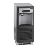
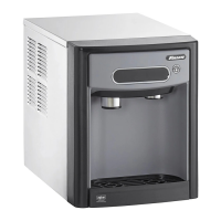
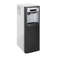
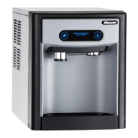
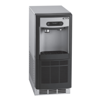
Understand the meaning of Follett configuration numbers for dispenser identification.
Essential safety guidelines for installation, operation, and servicing the ice dispenser.
Physical measurements of the 7UC100A and 7UD100A models.
Recommended operating environment conditions for optimal performance.
Details on water inlet size and recommended shut-off valve placement.
Recommended TDS and hardness levels for water supply.
Required space around the unit for ventilation and connections.
Power supply specifications, circuit, and grounding needs.
Information on refrigerant type and potential hazards.
Thermal output specification for the ice machine.
Visual representation of unit dimensions and key measurements.
Ensuring the unit fits in the intended space with proper clearances.
Requirements for a flush floor for proper operation and service.
Guidance for preparing electrical, water, and drain lines.
How to install the bracket to control unit positioning.
How to enter and exit mode for surface cleaning without dispensing.
How to enter and exit mode for ice machine cleaning.
Steps required to open the unit for service and maintenance.
Adjusting DIP switches for filter status indication.
Configuring the six-month maintenance reminder.
Step-by-step instructions for cleaning the ice machine and dispenser.
Step-by-step instructions for sanitizing the ice machine and dispenser.
How to clean the exterior panels and user interface.
Explains the meaning of various LED indicator lights on the unit.
Detailed procedure for taking apart the evaporator assembly.
Detailed procedure for reassembling the evaporator assembly.
Diagram illustrating the water flow path within the dispenser.
Diagrams for melt water, vent, and reservoir systems.
Diagram of the unit's refrigeration circuit components.
Procedure for safely removing the condenser fan motor.
Explains the meaning of different messages shown on the user interface.
Detailed schematic of the dispenser's electrical connections.
Illustrated list and part numbers for external dispenser parts.
Illustrated list and part numbers for internal dispenser parts.
Illustrated list and part numbers for the bin assembly.
Illustrated list and part numbers for the evaporator assembly.
List of other relevant parts, kits, and consumables.
| Type | Water Dispenser |
|---|---|
| Cooling Method | Compressor |
| Power | 115V |
| Installation Type | Freestanding |
| Electrical | 1 phase, 60 Hz |