EasyManua.ls Logo

Follett 7 Series - User Manual

Follett 7 Series
20 pages
Print Icon
To Next Page IconTo Next Page
Loading...
Installation and Service Videos:
www.follettice.com/servicevideolibrary
01234673R01
801 Church Lane • Easton, PA 18040, USA
Toll free (877) 612-5086 • +1 (610) 252-7301
www.follettice.com
Installation Guide
115 V, 230 V, 220 V
Please visit https://www.follettice.com/technicaldocuments
for the Operation and Service manual for your unit.
7 and 15 Series
Ice and Water Dispenser
with Chewblet
®
Ice Machine
CI100A, FS100A, UC100A, UD100A
Welcome to Follett
Follett equipment enjoys a well-deserved reputation for excellent performance, long-term reliability and outstanding
after-the-sale support. To ensure that this equipment delivers that same degree of service, review this guide
carefully before you begin your installation.
Should you need technical help, please call our Technical Service group at (877) 612-5086 or (610) 252-7301.
Please have your model number, serial number and complete and detailed explanation of the problem when
contacting Technical Service.
Getting Started
After uncrating and removing all packing material, inspect the equipment for concealed shipping damage. All freight
is to be inspected upon delivery. If visible signs of damage exist, please refuse delivery or sign your delivery receipt
"damaged." Follett Customer Service must be notied within 48 hours. Wherever possible, please include detailed
photos of the damage with the original packaging so that we may start the freight claim process.
Question and Answer IconNeed help?

Do you have a question about the Follett 7 Series and is the answer not in the manual?

Summary

Getting Started

Initial Inspection and Damage Reporting

Procedure for inspecting the unit upon delivery for shipping damage and reporting claims.

General Safety and Handling Precautions

Critical Operational Safety Warnings

Key warnings regarding unit handling, electrical safety, and user maintenance.

Pre-Installation Preparation

Locating Serial Number and Accessing Technical Documentation

Instructions for finding the unit's serial number and accessing online technical documentation.

Product Specifications

Unit Dimensions and Shipping Weight

Detailed physical dimensions and shipping weight for 7 and 15 Series models.

Ambient Operating Environment Limits

Recommended air temperature, water temperature, pressure, and humidity ranges.

Plumbing Connection Requirements

Specifications for water inlet fittings and optional drain kits.

Technical Requirements for Installation

Water Quality and Inlet Specifications

Guidelines for water mineral content and connection type.

Required Installation Clearances

Mandatory clearances for electrical, ventilation, and drain connections.

Electrical Supply and Wiring Details

Details on voltage, phase, amperage, circuit requirements, and grounding.

Refrigeration and Heat Rejection Data

Information on refrigerant type and heat rejection rate.

7 Series Detailed Dimensional Drawings

Countertop Model Dimensions (CI;FS)

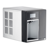
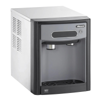
Diagrams and dimensions for 7 Series countertop models (CI/FS).

Freestanding Model Dimensions (CI;FS)

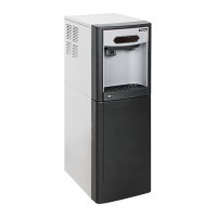
Diagrams and dimensions for 7 Series freestanding models (CI/FS).

15 Series Detailed Dimensional Drawings

Countertop Model Dimensions (CI;FS)

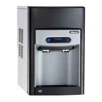
Diagrams and dimensions for 15 Series countertop models (CI/FS).

Freestanding Model Dimensions (CI;FS)

Diagrams and dimensions for 15 Series freestanding models (CI/FS).

7 Series UC;UD Model Drawings

UC;UD Model Views and Dimensions

Detailed views and dimensional data for 7 Series UC and UD models.

Installation Procedures

Countertop Installation Steps

Steps for installing the 7 Series countertop models onto a counter.

Freestanding Installation Steps

Steps for installing the dispenser as a freestanding unit.

Undercounter Installation Steps

Instructions for installing the dispenser within a cabinet space.

Potable Water Connection Procedure

Connecting the water supply line to the dispenser.

Optional Internal Water Filter Installation

Procedure for installing an optional internal water filter.

Maintenance and Cleaning Modes

Using Cleaning Mode

How to enter and exit Cleaning Mode for exterior cleaning.

Using Maintenance Mode

How to enter and exit Maintenance Mode for internal cleaning.

Accessing Internal Components Guide

Steps to remove panels for accessing internal parts.

Activating Filtered Ice;Water Display

Adjusting DIP switches to activate filter status display.

Deactivating Six-Month Maintenance Reminder

Adjusting DIP switches to disable the PM reminder.

Cleaning and Sanitizing Procedure

Required Cleaning Supplies and Mixing

List of supplies and instructions for mixing the SafeCLEAN Plus solution.

Ice Machine and Dispenser Cleaning Steps

Detailed procedure for cleaning the ice machine and dispenser components.

User Interface and Exterior Cabinet Cleaning

Instructions for cleaning plastic and stainless steel surfaces.

LED Indicator Description

LED Indicator Names and Colors

List of LED indicators on the front panel and their associated colors.

Interpreting LED Status and Error Codes

Explanation of what each LED status or color signifies.

User Interface Display Identification

Operation Display Modes Overview

Visual representation of different operational displays on the user interface.

Display Conditions and Required Procedures

Mapping of interface displays to unit conditions and required actions.

Electrical Wiring Diagram

Wiring Diagram for Unit Components

Diagram showing electrical connections for various unit components.

Miscellaneous Parts and Supplies

Part Numbers for Filters and Cleaning Solutions

List of part numbers for water filters and cleaning solutions.

Warranty Registration and Technical Support

Equipment Evaluation and Registration Process

Information on registering equipment and its benefits for service history.

Contacting Follett Technical Support

Contact details for Follett's technical service group.

Overview

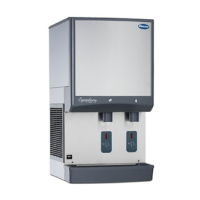
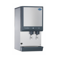
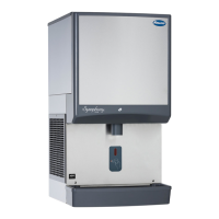
The Follett 7 and 15 Series Ice and Water Dispenser with Chewblet® Ice Machine (models CI100A, FS100A, UC100A, UD100A) is designed for commercial indoor use, providing ice and water dispensing capabilities. It operates on 115 V, 230 V, or 220 V power.

Function Description:

This appliance dispenses Chewblet ice and water. It is available in countertop and freestanding models, with variations in dimensions and capacities to suit different installation needs. The unit includes an ice machine that produces Chewblet ice, a type of soft, chewable ice. The dispenser features a user interface with LED indicators to communicate operational status and maintenance reminders.

Important Technical Specifications:

Dimensions (Width x Depth x Height):

  • 7CI100A: 14.50" (40 cm) x 22.12" (56.2 cm) x 17.50" (44.5 cm)
  • 7FS100A: 14.50" (40 cm) x 22.12" (56.2 cm) x 41.88" (106.4 cm)
  • 15CI100A: 14.50" (40 cm) x 23.50" (59.7 cm) x 22.50" (57.2 cm)
  • 15FS100A: 14.50" (40 cm) x 23.50" (59.7 cm) x 46.75" (118.7 cm)
  • 7UC100A: 14.55" (37 cm) x 22.05" (56 cm) x 33.50" (85.1 cm)
  • 7UD100A: 14.55" (37 cm) x 22.05" (56 cm) x 31.50" (80 cm)

Unit Shipping Weight:

  • 7CI100A: 90 lb (41 kg)
  • 7FS100A: 120 lb (54 kg)
  • 15CI100A: 100 lb (45 kg)
  • 15FS100A: 130 lb (60 kg)
  • 7UC100A: 100 lb (45 kg)
  • 7UD100A: 100 lb (45 kg)

Ambient Operating Conditions:

  • Air Temperature: Maximum 100°F (38°C), Minimum 50°F (10°C). Best performance between 80°F (27°C) and 50°F (10°C).
  • Water Temperature: Maximum 90°F (32.2°C), Minimum 40°F (4.5°C).
  • Water Pressure: Maximum 70 psi (483 kpa), Minimum 10 psi (69 kpa).
  • Relative Humidity: 55% at 78°F (25.5°C).
  • Operation outside these limitations is considered misuse and voids warranty.

Plumbing:

  • Water Inlet: 1/4" MPT or John Guest push-in fitting.
  • Drain: Optional Drain Accessory Kit (item# 00956375 or 00981977) requires 1/2" ID tubing.
  • Water shut-off recommended within 5 ft (1.5m) of dispenser.
  • Connect to potable water supply only.
  • Water Mineral Content: TDS: greater than 5 ppm (mg/l) but less than 400 ppm (mg/l). Hardness: Less than 200 mg/l (12 gpg). Not recommended for use with softened water.
  • Ingress Protection (IP) rating: IPX0 (no protection).

Electrical:

  • 115 V: 60 Hz, 1 phase, 5A, maximum fuse 15A. Requires a dedicated 15A circuit, fuse or breaker, and a grounded 3-prong outlet.
  • 230 V and 220 V: 50 Hz or 60 Hz, 1 phase, 5.5A. Requires a dedicated circuit and equipment ground. Cord provided on ice machine.
  • Clearances:
    • CI/FS Models: 3" (7.6 cm) behind and on each side for electrical connections, ventilation.
    • UD/UC Models: 3" (7.6 cm) behind for electrical and optional drain connection, 6" (153 mm) in front for ventilation.

Refrigeration:

  • Refrigerant: R134a.
    • 115 V: 5.0 ounces (142 grams).
    • 230 V/220V: 7.2 ounces (204 grams).
  • Heat Rejection: 1700 BTU/hr (498 W).

Usage Features:

  • Serial Number Location: Found by removing the drip tray and locating the serial number label.
  • QR Code Access: A QR Code on the drip tray provides access to manuals, technical bulletins, and online training.
  • Internal Water Filter Option: Follett recommends installing a Follett water filter system in the ice machine inlet water line. If an internal water filter option is present, it must be installed for the dispenser to operate.
  • "Fresh Filtered Ice and Water" Display: Can be activated via DIP switch #3 on the control board if using a Follett filter or an aftermarket filter.
  • Six-Month Maintenance/Filter Change Reminder: Can be deactivated via DIP switch #8 on the control board.
  • LED Indicators: Located behind the front panel, these LEDs provide visual cues for various operational states and warnings:
    • Clean (Green): Dispenser in Cleaning Mode, dispensing disabled.
    • PM (Red): Six-month periodic maintenance required.
    • Drip tray (Red): Drip tray full.
    • Water leak (Red): Internal leak detected.
    • High amps (Red): Auger gearmotor exceeded current limit; machine shuts down for one hour.
    • Service (Red): 8000-hour bushing check required.
    • Maintenance (Yellow): Unit in Maintenance Mode, no ice production or dispensing.
    • Low water (Yellow): Insufficient water supply.
    • Time delay (Yellow): Ice production delayed after full bin or dispense activity.
    • Sleep cycle (Green): Unit in standby after full bin and non-use (12 hours for 7 Series, 4 hours for 15 Series).
    • Making ice (Green): Gearmotor, compressor, and fan motor energized.
    • Low bin (Green): Bin switch closed, calling for ice.
    • Power on (Green): Power supplied to unit.
  • User Interface Display: Shows operational status like "ICE" (normal operation), "EMPTY DRIP TRAY," "PM" (maintenance required), "CHECK FOR LEAKS," and indicates Maintenance Mode or Cleaning Mode.

Maintenance Features:

  • Cleaning Mode: Disables the user interface to allow cleaning of the dispenser exterior without accidental ice dispensing. Activated by pressing and releasing the maintenance/clean switch.
  • Maintenance Mode: Disables all operations for safe cleaning and/or sanitizing of the ice machine and dispenser. Activated by pressing and holding the maintenance/clean switch. Resets the six-month periodic maintenance reminder.
  • Accessing Internal Components: Involves removing the front panel, drip tray, and chrome ice dispenser chute. This allows access for cleaning, sanitizing, and filter installation.
  • Cleaning and Sanitizing Procedure: Recommended every 6 months (or more often depending on water conditions). Requires SafeCLEAN Plus™ solution (3 gallons for 7 Series, 6 gallons for 15 Series), funnel, bucket, and 100°F (38°C) potable water. Involves draining the unit, pouring in cleaning solution, allowing it to soak, cleaning the condenser, submerging and rinsing the dispense chute, and flushing the system with potable water.
  • Safety Precautions: Always place the dispenser in Maintenance Mode before servicing or cleaning the ice machine. Wear rubber gloves and safety goggles when handling SafeCLEAN Plus™. Do not use bleach. Do not tilt the unit more than 30° off vertical during uncrating or installation to prevent compressor malfunction. Disconnect power before accessing the dispenser bin area or servicing.
  • Installation:
    • Countertop Models: Designed to fit under standard cabinets (7 Series only). Requires 3" (7.6 cm) clearance behind and on sides. Legs can be screwed into the chassis.
    • Freestanding Models: Requires 3" (7.6 cm) clearance behind and on sides. Can be secured to a wall or cove molding with a supplied bracket to prevent tipping.
    • Undercounter Models: Requires 3" (7.6 cm) clearance behind for electrical and optional drain connection. The finished floor inside the cabinet must be flush with the floor outside. An angle bracket can be installed inside the cabinet to prevent the dispenser from being pushed too far back.
  • Technical Support: Follett provides technical assistance via phone at (877) 612-5086 or (610) 252-7301. Model and serial numbers, along with a detailed problem description, are required when contacting service.
  • Warranty Registration: Customers are encouraged to register their equipment at www.follettice.com/support to track service history and provide feedback.

Follett 7 Series Specifications

General IconGeneral
BrandFollett
Model7 Series
CategoryWater Dispenser
LanguageEnglish

Related product manuals