10
5
5
.
.
R
R
E
E
C
C
E
E
I
I
V
V
E
E
R
R
O
O
U
U
T
T
L
L
I
I
N
N
E
E
5
5
.
.
1
1
A
A
l
l
p
p
h
h
a
a
5
5
0
0
0
0
~
~
5
5
6
6
0
0
M
M
o
o
d
d
e
e
l
l
s
s
E
E
x
x
t
t
e
e
r
r
n
n
a
a
l
l
A
A
s
s
s
s
e
e
m
m
b
b
l
l
y
y
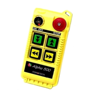
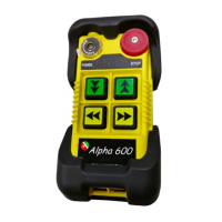
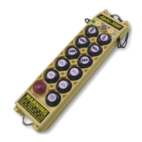
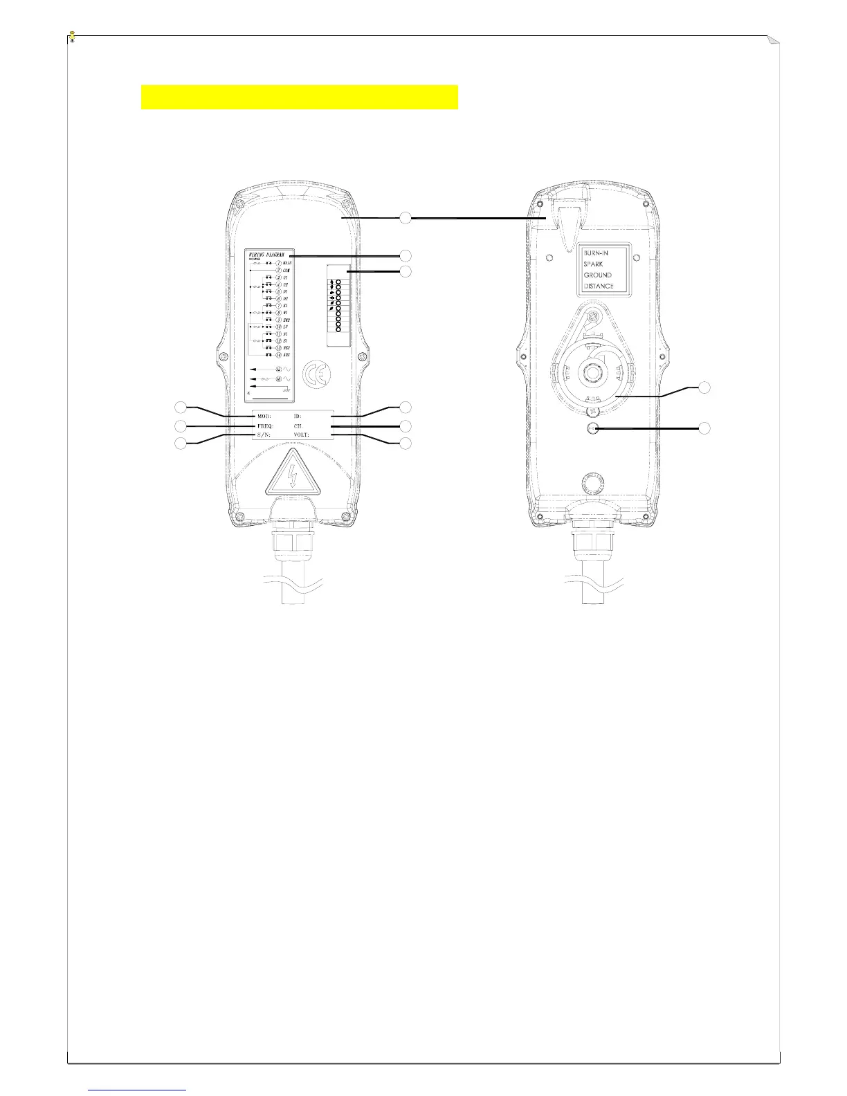
(Fig. 13) Front View (Fig. 14) Back View
1) Receiver enclosure 5) System frequency 9) Supplied voltage
2) Wiring diagram 6) System serial number 10) Anti-vibration spring
3) Receiver LED displays* 7) System ID code 11) Grounding (GND)
4) Type model 8) System RF channel
* A ~ AUX Relay Contact Indicator (for Alpha 540A/560A models only).
* M ~ MAIN and 2
nd
Speed Relay Contact Indicator.
Green "on" → MAIN activated (All models).
Red "on" → 2
nd
speed activated (for Alpha 560S/A models only).
* SQ ~ RF Signal Indicator (Red).
"on" → RF signal detected and received.
"off" → No RF signal detected or received.
Blinking at transmitter power "off" → Other radio interference.
* AC ~ Power Source Indicator (red) "on" → AC input power supplied.
"off" → No AC input power.
1A
POWER
AC220V 50/60HZ
must be grounded
Anti-vibration s pring
5A
N/S
5A
5A
5A
LV,AUX
E/W
MAIN
U/D
5A
AC
SQ
M
A
W
S
N
E
U
D
AC
SQ
M
A
4
5
6
7
9
8
2
3
1
10
11