23
7
7
.
.
3
3
R
R
e
e
c
c
e
e
i
i
v
v
e
e
r
r
R
R
F
F
C
C
h
h
a
a
n
n
n
n
e
e
l
l
S
S
e
e
t
t
t
t
i
i
n
n
g
g
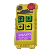
There are 30 sets of user-adjustable receiving RF channels that can be set manually via a 5-position
dip-switch located to the right of the receiving RF module. Change the receiving RF channel simply
by resetting these 5-position dip-switch. For the location of the receiving RF module, please refer to
fig. 15, 16, and 18 on page 11, 12, and 14.
Example: For the above dip-switch setting (
00101
) counting from dip-position #1 through #5, the above RF
channel would be “205”, which also represents frequency “301.205 MHz”. Please refer to the
frequency (RF) channel table on page 26 or the CHANNEL → DIP label located on the receiving RF
module itself.
7
7
.
.
4
4
H
H
o
o
w
w
t
t
o
o
R
R
e
e
m
m
o
o
v
v
e
e
t
t
h
h
e
e
T
T
r
r
a
a
n
n
s
s
m
m
i
i
t
t
t
t
i
i
n
n
g
g
R
R
F
F
B
B
o
o
a
a
r
r
d
d
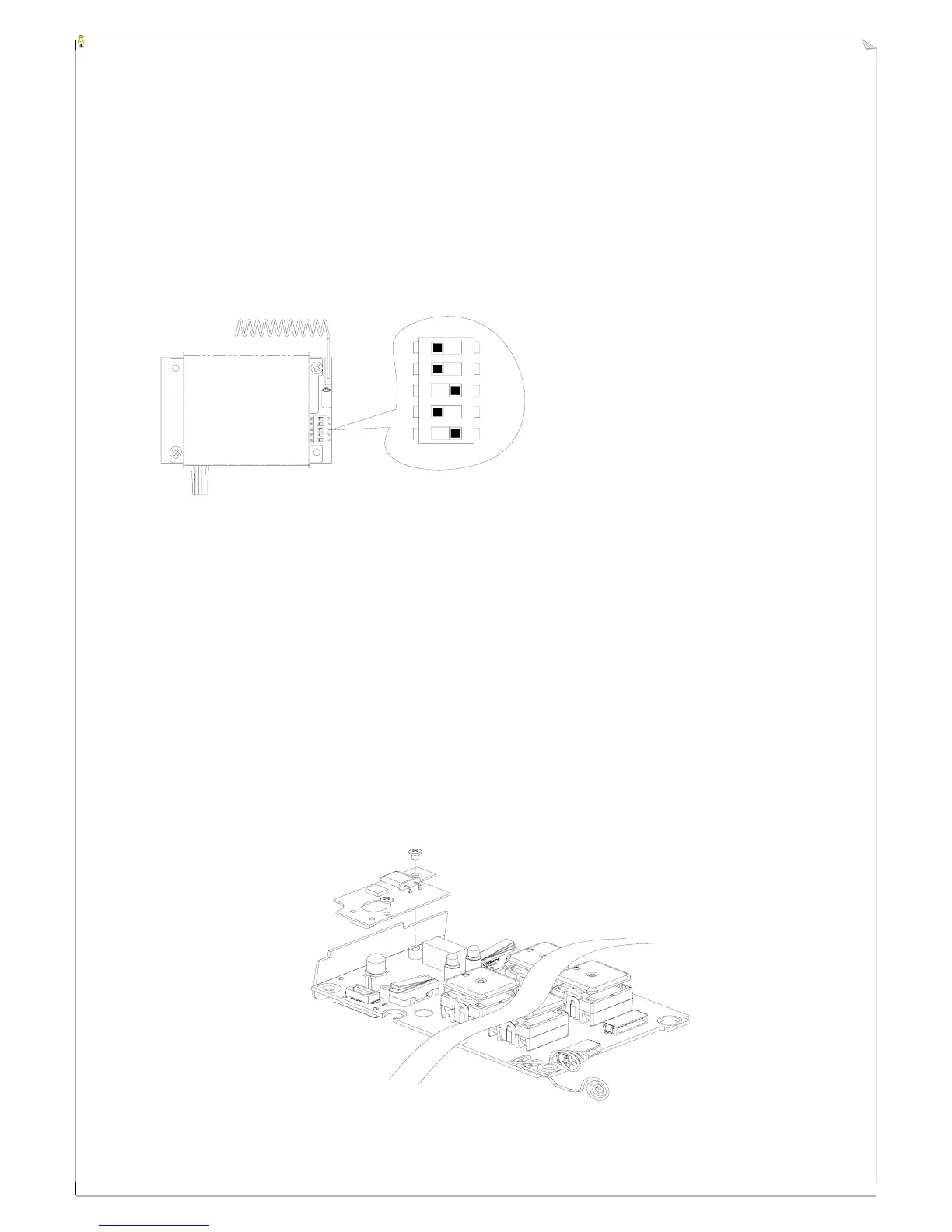
The transmitter RF channel can be easily replaced or exchanged simply by replacing the small
removable RF board located atop the transmitter encoder board. The small RF board can be easily
removed by unscrewing the two small bolts that secured the RF board and the encoder board together
(refer to the diagram below). Please keep in mind that the RF channel of the transmitter must be
identical to the receiver. If the RF channel for both transmitter and receiver are different, please
readjust accordingly (refer to section 7.3 above).
1
2
3
4
5