12
1
2
3
4
5
5
.
.
3
3
A
A
l
l
p
p
h
h
a
a
5
5
4
4
0
0
&
&
5
5
6
6
0
0
M
M
o
o
d
d
e
e
l
l
s
s
I
I
n
n
t
t
e
e
r
r
n
n
a
a
l
l
A
A
s
s
s
s
e
e
m
m
b
b
l
l
y
y
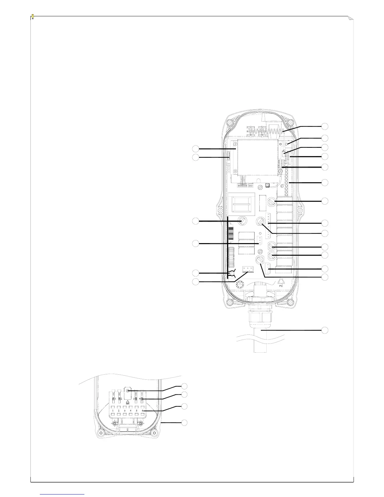
(Fig. 16) Internal Parts Assembly
1) Receiving RF module
2) External programming port
3) Secondary power AC fuse (0.50A)
4) Contact output seat (CN8)
5) Primary power AC fuse (1.0A)
6) AC power input seat (CN2)
7) Internal Antenna
8) System Status LED display*
9) External antenna port
10) ID code dip-switch
11) RF channel dip-switch
12) Contact relay LED display
13) Pushbutton #1and #2 fuse (5.0A)
14) Contact output seat (CN3)
15) MAIN contact fuse (5.0A)
16) Pushbutton #3 and #4 fuse (5.0A)
17) Pushbutton #5 and #6 fuse (5.0A)
18) Contact output seat (CN4)
19) LV & AUX fuse (5.0A)
20) Cable gland & output cable
* Please refer to page 32 for system status
LED display information.
1) Spare fuse & jumper compartment
2) Spare Jumper slots
3) Spare fuse slots
4) Receiver top casing
3
5
6
7
19
4
11
10
12
13
14
15
17
18
9
16
20
F
U
S
E
F
U
S
E
F
U
S
E
F
U
S
E
F
U
S
E
F
U
S
E
1
2
8