24
7
7
.
.
5
5
A
A
l
l
p
p
h
h
a
a
5
5
8
8
0
0
M
M
o
o
d
d
e
e
l
l
s
s
P
P
u
u
s
s
h
h
b
b
u
u
t
t
t
t
o
o
n
n
F
F
u
u
n
n
c
c
t
t
i
i
o
o
n
n
S
S
e
e
t
t
t
t
i
i
n
n
g
g
s
s
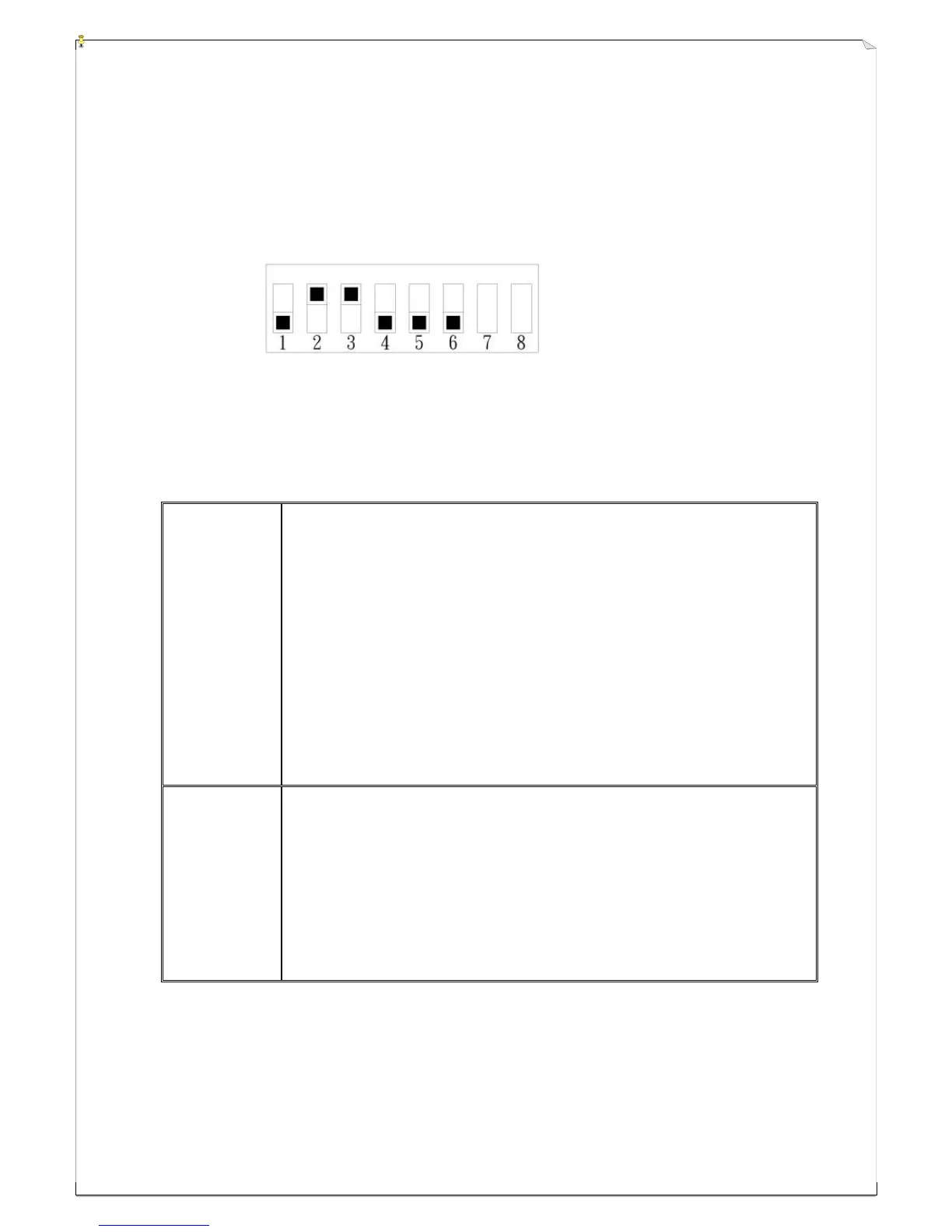
Numerous Alpha 580 models’ pushbutton contact relay settings can be set via an 8-position dip-switch
located on the receiver decoder/relay board (refer to fig. 18 on page 14).
DIP-1 → “0”
Example: DIP-2 → “1”
DIP-3 → “1”
DIP-4 → “0”
DIP-5 → “0”
DIP-6 → “0”
Top slot represents “1” value and lower slot represents “0” value.
Alpha 580 models dip-switch function table
Alpha 580A-1
&
Alpha 580A-2
DIP1 → “0” → pushbutton 1&2, 3&4, 5&6 interlocked
“1” → pushbutton 1&2, 3&4, 5&6 not interlocked
DIP2 → “0” → pushbuttons 7&8 interlocked
“1” → pushbutton 7&8 not interlocked
DIP3 → “0” → pushbutton 7&8 with momentary relay contact (DIP2 set at “1”)
“1” → pushbutton 7&8 with latching/toggled relay contact (DIP2 set at “1”)
DIP4 → “0” → pushbutton 9&10 interlocked
“1” → pushbutton 9&10 not interlocked
DIP5 → “0” → pushbutton 9 with momentary relay contact (DIP4 set at “1”)
“1” → pushbutton 9 with latching/toggled relay contact (DIP4 set at “1”)
DIP6 → “0” → 10
th
pushbutton with momentary relay contact (DIP4 set at “1”)
“1” → 10
th
pushbutton with latching/toggled relay contact (DIP4 set at “1”)
Alpha 580B
DIP1 → “0” → pushbutton 7&8 interlocked
“1” → pushbutton 7&8 not interlocked
DIP2 → “0” → pushbuttons 7 with momentary relay contact (DIP1 set at “1”)
“1” → pushbutton 7 with latching/toggled relay contact (DIP1 set at “1”)
DIP3 → “0” → pushbutton 8 with momentary relay contact (DIP1 set at “1”)
“1” → pushbutton 8 with latching/toggled relay contact (DIP1 set at “1”)
DIP4 → “0” → pushbutton 9 with momentary relay contact
“1” → pushbutton 9 with latching/toggled relay contact