FORCE1 RC
12
DRONE ASSEMBLY
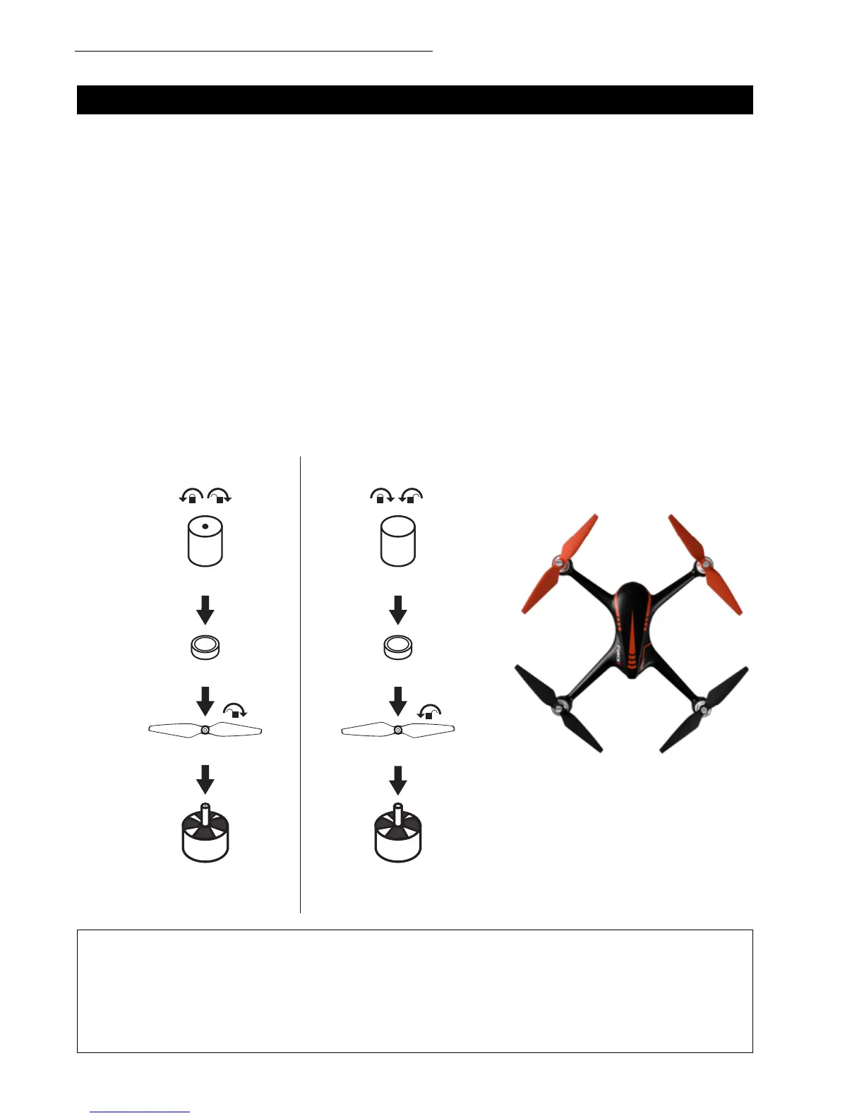
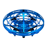
PROPELLER INSTALLATION/REMOVAL
PROPELLER A INSTALLATION
Place propeller A on the corresponding motor shaft (Fig. 5). The side marked A should be facing
upwards. Fix the rotor propellers by rotating them as per the “lock direction shown on the propellers.”
Place the rubber ring into the center bore of the propeller, then tighten the screws counterclockwise.
Propeller A screws have a dot on top.
PROPELLER B INSTALLATION
Place propeller B on the corresponding motor shaft (Fig. 5). The side marked B should be facing
upwards. Fix the rotor propellers by rotating them as per the “lock direction shown on the propellers.”
Place the rubber ring into the center bore of the propeller, then tighten the screws clockwise. Propeller
B screws do not contain a dot on the top.
REMOVAL
Hold the brushless motor and unscrew the A screws clockwise and the B screws counterclockwise. Then
rotate and remove the propellers as per the “unlock” direction shown on the propellers.
• Please be sure to install the correct propellers (matching A and B)
• Be careful with propellers, as they can be sharp
• Purchase extra propellers at force1rc.com
CAUTION:
SCREW WITH DOT
PROPELLER A REMOVAL PROPELLER B REMOVAL
RUBBER RING
PROPELLER A (CLOCKWISE) PROPELLER B (COUNTERCLOCKWISE)
CLOCKWISE ROTATING
MOTOR IS MARKED
WITH A WHITE DOT.
COUNTERCLOCKWISE
ROTATING MOTOR IS MARKED
WITH A BLACK DOT.
RUBBER RING
SCREW WITHOUT DOT
FRONT
REAR
A B
A
A
B
B
BA
FIGURE 5