5-3
FORMULA
SYSTEM OPERATION AND EQUIPMENT
CRUISER/SUPERSPORT
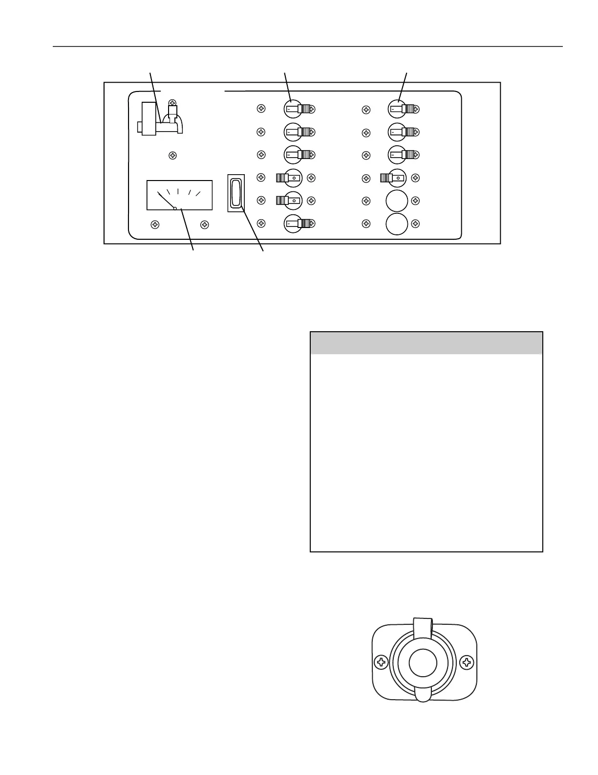
The 12 VDC system consists of a voltmeter, a
battery test switch, two main circuit breakers and
a series of switch-type circuit breakers, including a
dedicated circuit for the CO detector(s). The
voltmeter allows you to check the voltage of the
house (also port engine start) battery by pressing
the battery test switch alternately up and down.
The bilge pump(s), CO detector, anti-electrolysis
system and stereo memory will remain energized,
even if the battery switches are turned OFF. All
other items will be disabled.
The CO detector (sensor) circuit breaker must be
in the ON position at all times with the slide lock
engaged. Disengage the slide lock and turn OFF
the CO detector circuit breaker only during long
periods of storage.
To operate the 12 VDC system:
●
Turn ON the port engine/house battery
switch.
●
Turn ON the DC main circuit breakers.
●
Activate the individual component circuit
breaker.
The boat’s bilge pumps are powered by the
DC Electrical System. A boat left moored in
the water for extended periods without
shorepower to maintain its batteries may
find itself without adequate battery power in
time of need. Even though one shuts off the
battery switches prior to leaving a boat,
there are systems aside from bilge pumps
that remain connected to the batteries, i.e.
electronics memory, Mercathodes, alarms,
etc. If the batteries do not have an
opportunity to be recharged, these systems
will eventually drain the battery. Boats left
moored in the water are to be checked
regularly (twice weekly) to ensure the
batteries are adequately charged.
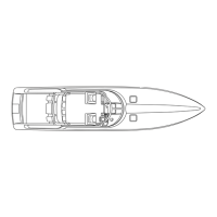
12-Volt Accessory Power Receptacle—Your
Formula is equipped with 12-volt accessory power
receptacle(s). The receptacle provides electricity
to operate 12 VDC accessory items.
12-Volt Accessory Power Receptacle
Figure 5-2