17
20
18
19
16
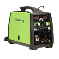
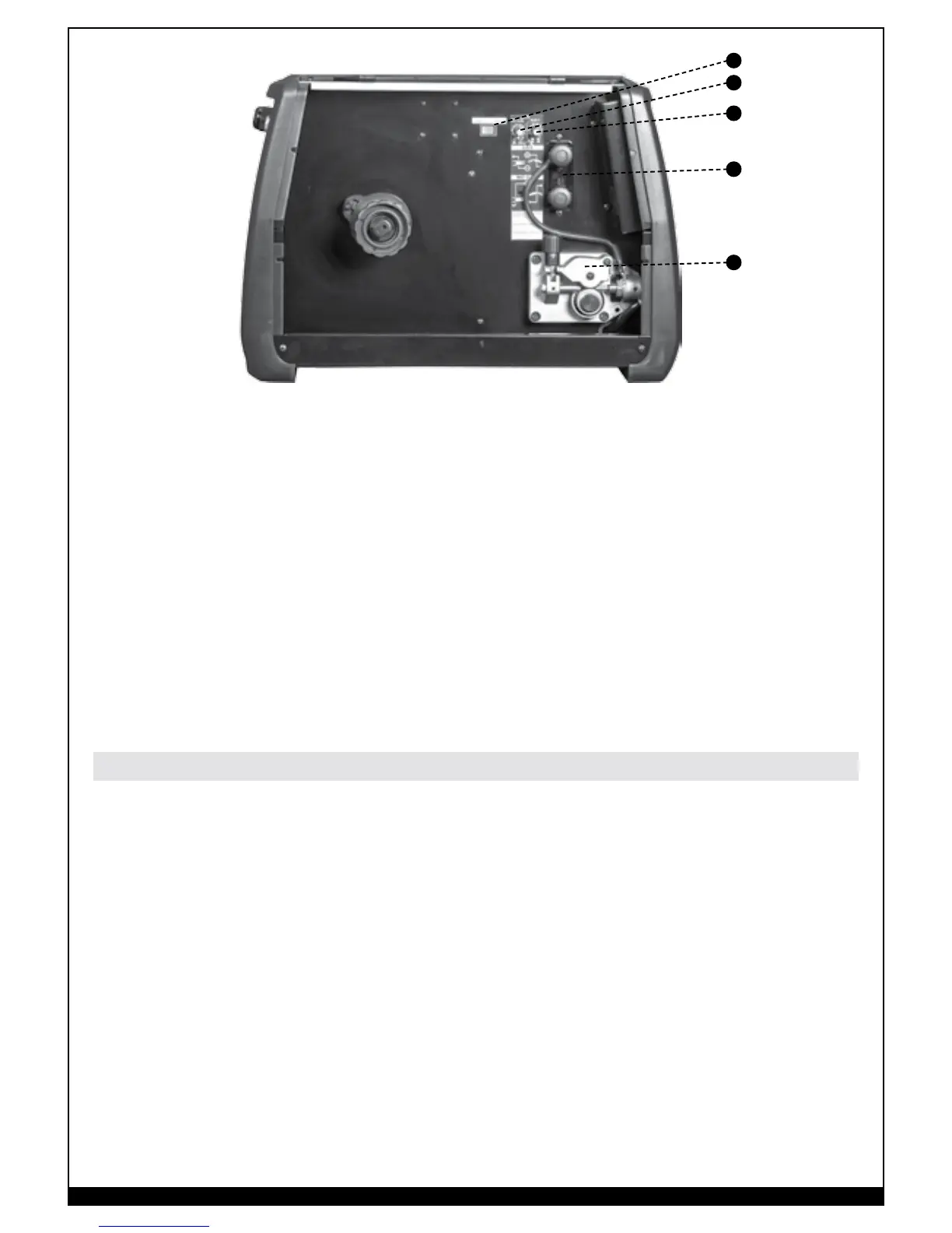
FIGURE 3
16. 2 roll Aluminum wire feeder
17. Slope up Time regulation potentiometer
18. Burn Back Time Regulation potentiometer (B.B.T.)
19. Polarity Change Terminals for the Euro Socket:
a. positive polarity for MIG Welding, “GMAW”;
b. negative polarity for FLUXCORE WIRE Welding, “FCAW”
20. Local / Remote switch:
a. Local: when selected all welding parameters have to be adjusted using knobs 7 and 8 on
the front control panel
b. Remote: when selected Left Knob (8) is not active. In STICK Welding, “SMAW” and TIG
Welding, “GTAW” Mode current is adjustable using the foot pedal. In MIG Welding,
GMAW” Mode the wire speed is adjustable using the potentiometer on the Spool Gun torch.
• Connect the ground cable to the correct Dinse socket (9 & 10) for the welding you plan to do.
Attach the ground clamp to the bare metal to be welded, making sure of good contact;
• Make sure that the wire-roller groove in the roller corresponds to the diameter of the wire
being used. Refer to paragraph 6.
• Plug the machine into a suitable outlet.
• Open the gas valve on the gas cylinder all the way. Adjust the gas flow regulator valve to the
desired flow. Clockwise to increase, Counter clockwise to decrease the flow.
Welding Preparation