potentiometer located inside the access panel (17).
2. At the end of the the Slope-Up Time, the wire feed speed reaches the value adjusted with the
Left knob (8).
• To stop welding, release the trigger. The arc stays ON accordingly to the set B.B.T. (Burn back
time). B.B.T. is the amount of time that the weld output continues after the wire stops feeding. It
prevents the wire from sticking in the puddle and prepares the end of the wire for the following
arc start.
The machine needs to be set up as follows:
• 100% ARGON as welding protective gas.
• Ensure that your torch is set up for aluminum welding:
1. The length of the torch should not exceed 12” (it is advisable not to use longer torches).
2. Install a teflon wire liner (follow the instructions for the replacing of the wire liner).
3. Use contact tips that are suitable for aluminum wire and make sure that the diameter of the
contact tip hole corresponds to the wire diameter that is going to be used.
• Ensure that drive rolls are suitable for aluminum wire.
WARNING: Electric shock can kill! Always turn the POWER switch OFF and unplug the
power cord from the ac power source before installing wire.
Before installing any welding wire into the unit,
the proper sized groove must be placed into
position on the wire drive mechanism. Adjust the
drive roller according to the following steps:
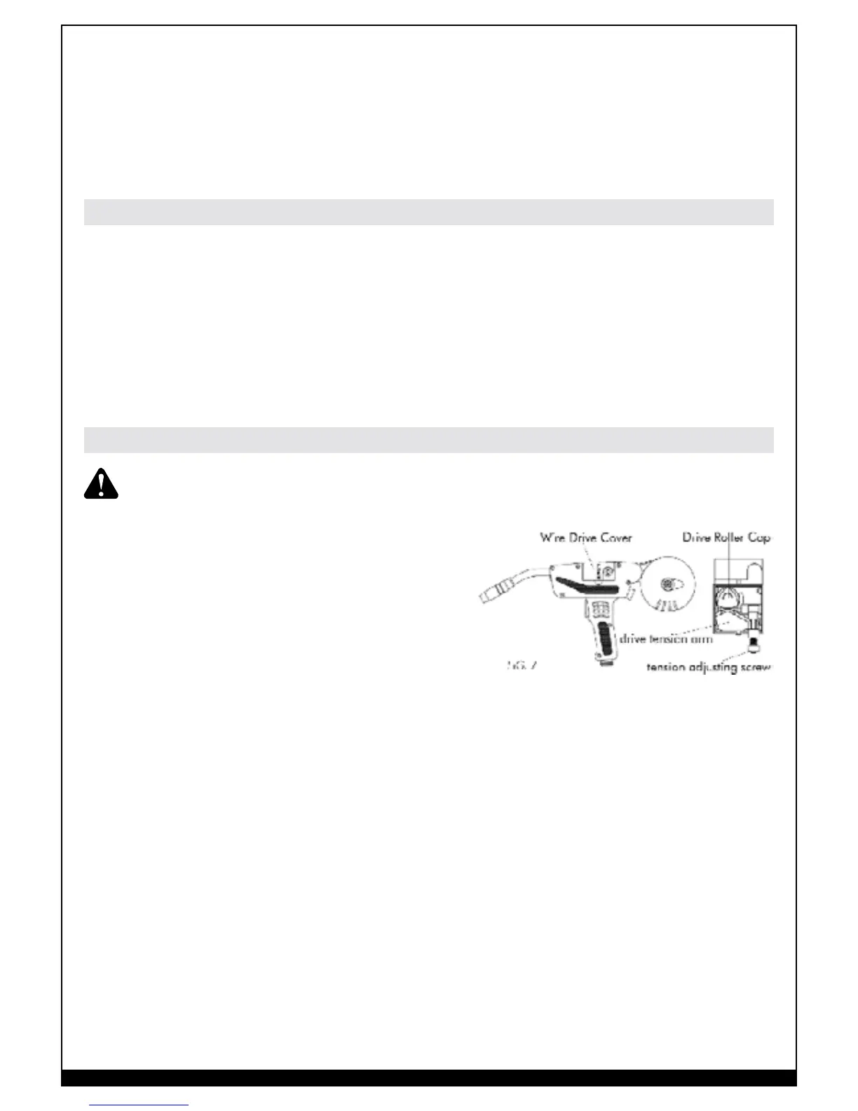
1. Open the Wire Drive cover on the Spool Gun.
2. Remove the drive tension by loosening the
tension adjusting screw and lifting the Drive
Tension Adjustor up, away from the Drive Tension
Arm. Pull the drive tension arm away from the drive roller.
3. Rotate the Drive Roller Cap counterclockwise and remove it from the Drive Wire Drive Cover
Drive Roller Cap FIG. 7 tension adjusting screw drive tension arm Roller. Pull the Drive Roller
off of the Drive Roller Shaft . Note: The drive roller has two wire size (.030” – .035”) grooves
built into it.
4. Find the side of the drive roller that is stamped with the same wire diameter as that of the wire
being installed. Push the drive roller onto the drive roller shaft, with the side stamped with the
desired wire diameter facing you.
5. Reinstall the Drive Roller Cap and lock in place by turning it clockwise.
6. Remove the nozzle and contact tip from the end of the gun assembly.
7. Open the Wire Spool Casing, located at the rear of the Spool Gun, by turning the retaining
knob counterclockwise.
8. Unwrap the spool of wire and then find the end of the wire.
9. After checking to make sure that your welder is disconnected from the ac power source, free
the leading end of the wire from the spool, but do not let go of it until told to do so, or the
wire will unspool itself.
10. Using a pair of pliers, cut off the bent portion at the end of the wire so that you are left with a
straight section of wire.
11. Unroll about 6” of welding wire from the wire spool.
12. Insert the leading end of the wire into the inlet guide tube (located in the Wire Spool Casing).
Aluminum Welding
Arrangement for Welding with Spool Gun