15
WWW.FORNEYIND.COM
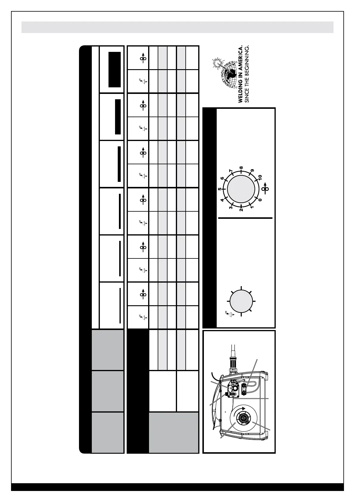
MIG Welding (GMAW) Welding Setting Chart
Regulation Knob
Voltage
Setting
Wire Feed
Setting
Voltage
Setting
Wire Feed
Setting
Voltage
Setting
Wire Feed
Setting
Voltage
Setting
Wire Feed
Setting
Voltage
Setting
Wire Feed
Setting
Voltage
Setting
Wire Feed
Setting
Solid Wire
75% Ar + 25%
CO
2
(ER70S-6)
.023” (0.6 mm) 1 2 2 3.5 3 5 4 6 5 7 6 7.5
.030” (0.8 mm) - - 2 2.5 3 3.5 4 4.5 5 6 6 6
.035” (0.9 mm) - - 2 2 3 3 4 4 5 4 6 7
Flux Core Wire
(No Gas)
(E71T-GS)
.030” (0.8 mm) - - 2 2.5 3 5 4 5 5 6 6 7.5
.035” (0.9 mm) - - 2 1.5 3 4 4 3.5 5 5 6 7
(Wire)
GAS
WIRE
ø
MATERIAL THICKNESS
24 Gauge
.0236” (.6 mm)
22 Gauge
.0315” (.8 mm)
18 Gauge
.0236” (1.2 mm)
16 Gauge
.0139” (1.6 mm)
1/8” (3 mm) 1/4” (6.4 mm)
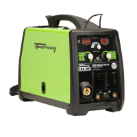
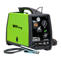
190 MIG SET-UP CHART
Arc Voltage Control Wire Speed Control
This control sets the
arc welding voltage. It
is proportional to the
amount of heat in the arc.
Position 6 is the highest
arc voltage or heat setting.
This sets the wire feed
speed (WFS) of the
electrode wire through
the MIG gun.
Position 0 is 80 IPM
Position 10 is 700 IPM
Forney Industries, Inc.
www.forneyind.com
Pressure Adjust Device
POLARITY
CHANGE
+/-
Pressure Arm
Gun Cable End
Wire Spool Inlet Wire Guide Feedroll
Top-loading