All information contained within this document is proprietary to Fingerprint Cards AB.
2 Development Kit Hardware
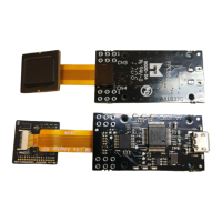
2.1 BM-Lite Module
BM-Lite module (Part number: 100018754)
The BM-Lite module has a standard 10 pin 0.5 mm pitch Flat Flex Connector as main interface.
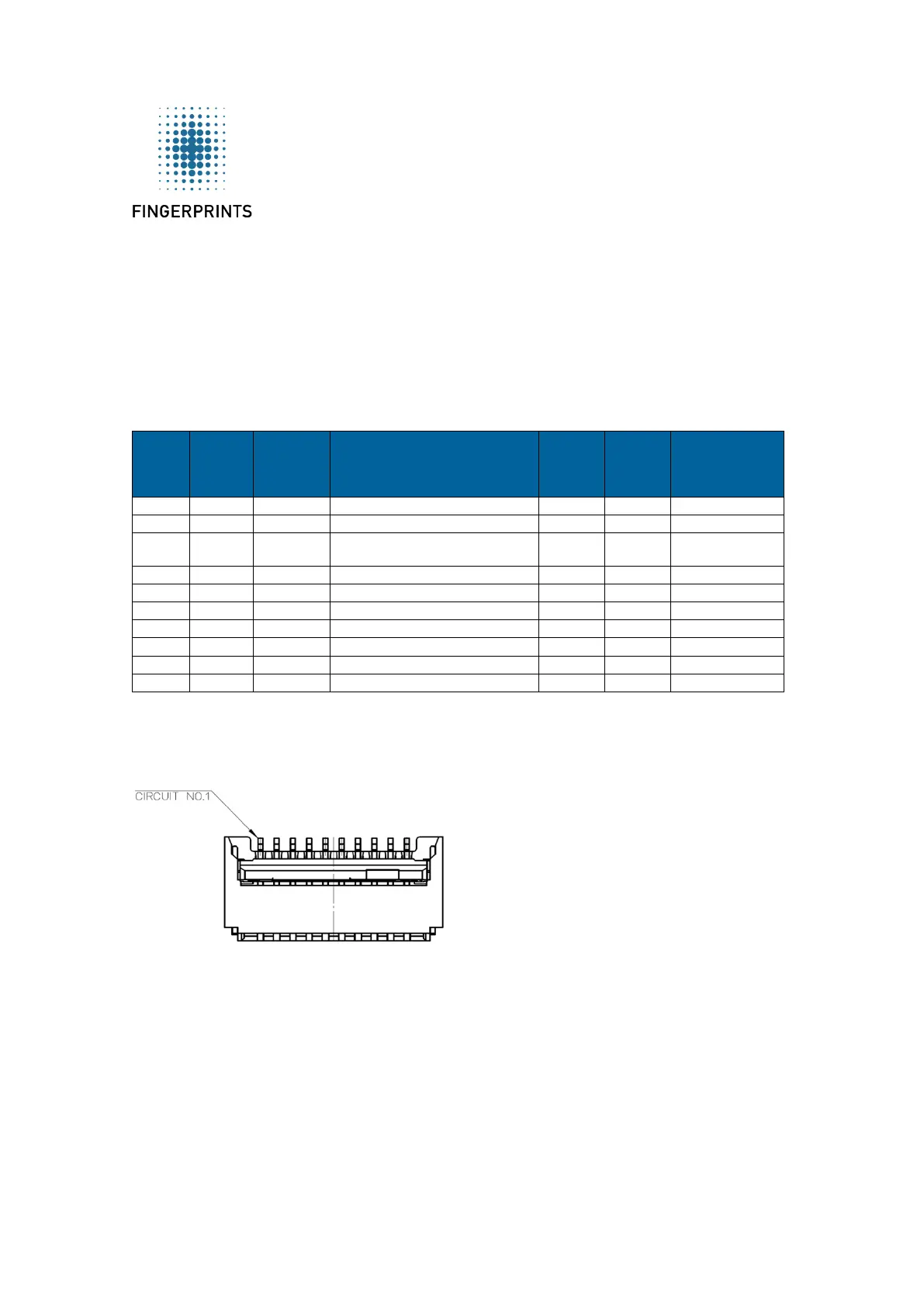
The pin-out is described in the table below.
Serial clock used for SPI
The SPI Serial tri-state output which is
enabled with CS_N low
The SPI Serial data Input
Chip Select active when low
Interrupt request output (SPI only)
Reset module. Active low*.
Core supply voltage. Typical 3.3V
BM-Lite interface
* Keep low at least 20µs to reset whole module
**Default baud rate is 115200
BM-Lite FFC connector. Pin 1 is to the left.
BM-Lite supports both UART and SPI interfaces. Both interfaces are enabled at power-on, but
only one of them can be used at the same time. BM-Lite will auto detect which interface is
being used by detecting data traffic. It is therefore important that the input signals for the
unused interface are pulled into a fixed state to avoid interference.
2.1.1 SPI Interface
When using the SPI interface, the UART RX signal should be held at a fixed state to avoid
unintentional interference on the UART interface.
 Loading...