11
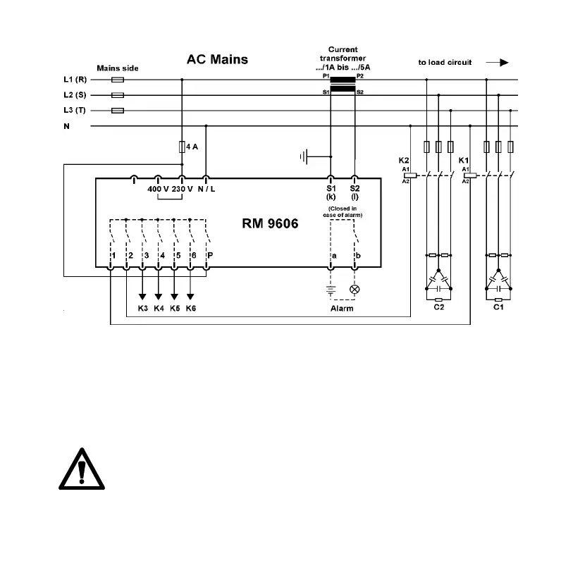
Figure 3: Circuit Diagram
3.3 Current Transformer Connection
The outputs S1 and S2 of the current
transformer are connected to the terminals
S1 and S2 of the control relay. In order to
keep the load on the current transformer
as low as possible the supply lines should
have a cross-section area of 2.5 mm².
ATTENTION:
The rated current in the current trans-
former path should not exceed 5 Amps.
Notice:
After connection the short-circuiting bridge
might have to be removed from the cur-
rent transformer.
3.4 Alarm Contacts
A potenial-free alarm signal contact is ac-
cessible on the terminals "a" and "b". The
contact closes when either there is no
mains voltage applied to the control relay
or when an alarm is signalled.(section 6.3)