22
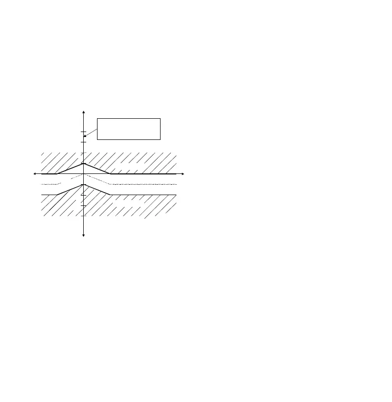
this case the control range is not
prolonged at the reactive power axis into
the feed back side, but is mirrored from
the supply side into the feedback side.
Figure 10: Control response after setting
target power factor = 0.95 cap; L = 1.0;
PS = 0
Active current
Reactive current
3
2
-3
-2
ind
cap
Regeneration
One scale division
corresponds to 0.65 *
smallest capacitor stage
5.4 Switching Time Delay
The switching time delay period can be set
between the values of 5 to 500 seconds in
5 second steps. When a capacitor stage
is switched on or off the control relay waits
for the switching time delay before the
switching process takes place. If more
stages are required the switching time
delay is shortened depending on the
number of stages required.
For example:
2 stages required = switching time delay /2
(reduced by one-half) or
3 stages required = switching time delay /3
(reduced by two-thirds).
In order to keep the wear on the contacts
to a minimum, the switching delay time
should be set to less than 45 seconds only
in exceptional cases. The discharge
period, which ensures that the capacitors
are fully discharged before they are
switched on again, overrides the switching
delay time (see section 5.12).
5.5 Automatic Stage Current (c/k)
Identification "ON/OFF"
The RM 9606 has an automatic c/k identi-
fication, i.e. it calculates the appropriate
response current the first time the control
relay is energized. This procedure is re-
peated until the amount of capacitive
power for each stage is determined and
the c/k value has been calculated. The
automatic c/k identification feature can be
set to "ON" or "OFF".
When "ON" the RM 9606 operates with
the stage currents automatically calculated.
When "OFF" the c/k value must be pro-
grammed manually (under programme
mode 6) according to Table 3 on page 24
or according to the Equation 1. Also pro-
gramme modes 7 (switching sequence)
and 8 (number of contactors used) have
to be entered manually.