19
5.1 Setting of Target Power Factor
The desired target power factor can be set
from cap. 0.9 to ind. 0.8 in 0.01 steps.
The mode of operation of this adjustment
can be seen in Figure 4 and Figure 5.
If the control relay operates within the
band range shown no switching opera-
tions will be activated.
However, if the control relay operates out-
side the band range, the RM 9606 will try
to come within the band range with the
minimum of switchings.
Figure 4: Control response after setting
target power factor = 1; L = OFF; PS =0
Active current
Reactive current
2
3
-2
-3
ind
cap
One scale division
corresponds to 0.65 *
smallest capacitor stage
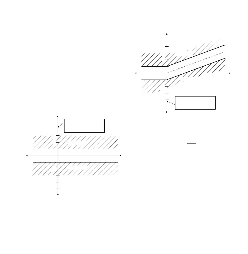
Figure 5: Control response after setting
target power factor = 0.92 ind; L = OFF;
PS = 0
Active current
Reactive current
2
3
-2
-3
ind
cap
Regeneration
One scale division
corresponds to 0.65 *
smallest capacitor stage
In Figure 5 the behaviour of the control
relay during feedback operation can also
be seen. The "kink" in the band
(characteristic line) is not reflected in the
feedback operation but is extended at the
point of intersection of the reactive power
centre line (axis) with the feed-back
operation line.
By shifting the band into the capacitive
range (see Figure 7 in section 5.2) the
occurrence of an inductive reactive power
during the feedback operation can be
virtually avoided.
When a capacitive target power factor
mode is set, the control band is reflected
from the supply side to the feedback side.
(see Figure 10).