18
If the current transformer is installed in correct direction and the connections S1(k) and
S2(l) are correctly connected with the control relay, the following kinds of Connection
modes are valid:
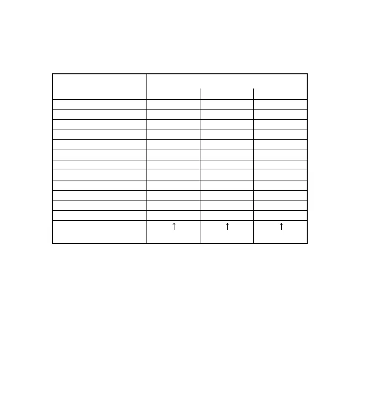
Connection at the voltage path
Connection mode
L/N – L L/N – L L/N – L
0 L1 – N L2 – N L3 – N
1 L1 – L3 L2 – L1 L3 – L2
2 N – L3 N – L1 N – L2
3 L2 – L3 L3 – L1 L1 – L2
4 L2 – N L3 – N L1 – N
5 L2 – L1 L3 – L2 L1 – L3
6 N – L1 N – L2 N – L3
7 L3 – L1 L1 – L2 L2 – L3
8 L3 – N L1 – N L2 – N
9 L3 – L2 L1 – L3 L2 – L1
10 N – L2 N – L3 N – L1
11 L1 – L2 L2 – L3 L3 – L1
CT Location in phase:
↑
L1
↑
L2
↑
L3
Table 2: Connection mode
Note:
If S1(k) and S2(l) are connected the wrong way around or the CT is installed in wrong
direction, connection mode number must be added by 6. If the result is higher than 11,
12 must be subtracted. The result corresponds to the connection mode number which
have to be entered.