20
5.2 Parallel Shift (PS)
This setting causes a parallel shift of the
band range as shown in Figure 4 by the
set value.
It will shift to the inductive direction if the
plus sign is used and to the capacitive
direction if the minus sign is used.
The values -2 to +4 can be set in 0.5
steps. The effects are illustrated by the
two examples in Figure 6 and Figure 7.
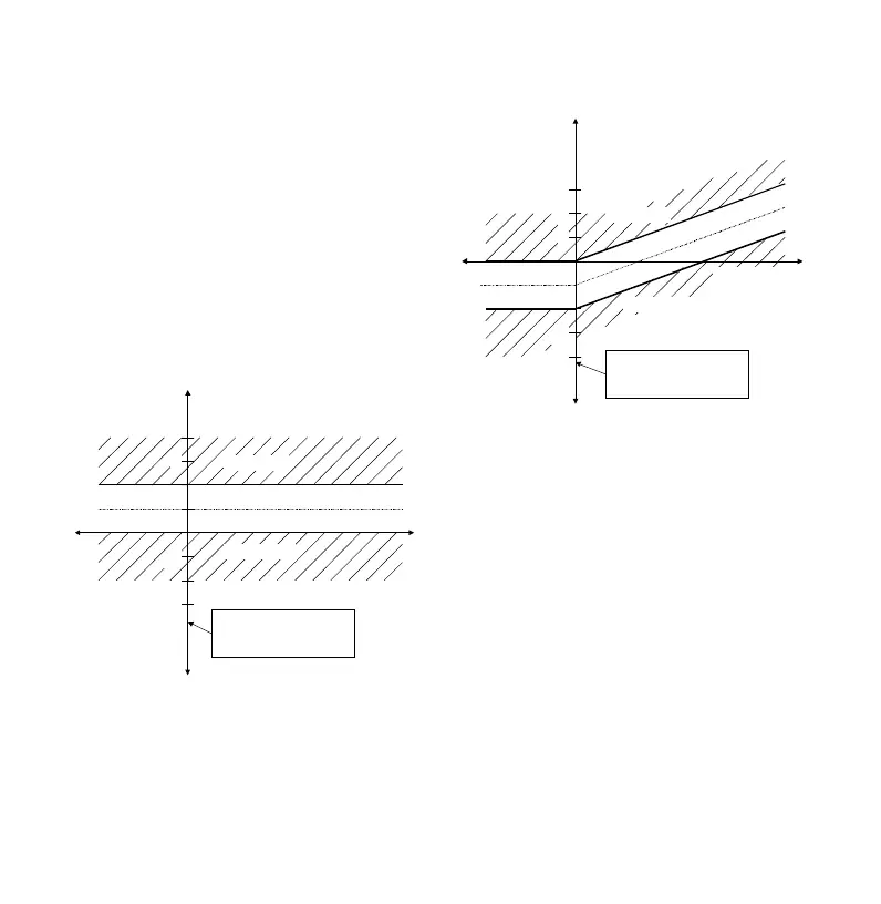
Figure 6: Control response after setting
target power factor = 1; L = OFF;
PS = +1.0
Active current
Reactive current
3
-1
-2
ind
cap
Regeneration
Switched off
One scale division
corresponds to 0.65 *
smallest capacitor stage
1
-3
The set target power factor is therefore
the upper limit of the control band.
Figure 7: Control response after setting
target power factor = 0.92 ind; L = OFF;
PS = -1.0
1
Reactive current
2
-2-3
ind
cap
Regeneration
One scale division
corresponds to 0.65 *
smallest capacitor stage
Active current
The set target power factor is the lower
limit of the control band range.
(This is the recommended setting
when using asynchronic generators in
parallel.)
5.3 Limitation (L)
This setting gives new possibilities that
could not be attained before due to
opposing requirements.
The range of values for L are -2 to +2 in
steps of 0.5 and the setting "OFF". Setting
the limitation value of 1 and a target power
factor of 1.0 has the same effect as the
parallel shift. For a target power factor
other than 1.0 there is a "kinked"
characteristic as shown in Figure 8.