reactive power
control relay
Table 3: Minimum and maximum current transfomer step-down ratios
Power Factor Correction Systems
Commissioning and Maintenance
Smallest
stage
(in kVAr)
Largest
stage
(in kVAr)
Min. and
max. current
transformer
ratios
Min. and max.
nominal pri-
mary currents
for ... / 5 A
transformers
Min. and max.
nominal pri-
mary currents
for ... / 2.5 A
transformers
Min. and max.
nominal pri-
mary currents
for ... / 1 A
transformers
2.50 2.50
1.5 ... 80 10 ... 400 5 ... 200 5 ... 80
2.50 5.00 3 ... 80 15 ... 400 10 ... 200 10 ... 80
2.50 7.50 4.5 ... 80 25 ... 400 15 ... 200 15 ... 80
2.50 10.00 6 ... 80 30 ... 400 20 ... 200 20 ... 80
2.50 15.00 9 ... 80 50 ... 400 25 ... 200 25 ... 80
2.50 20.00 12 ... 80 60 ... 400 30 ... 200 30 ... 80
5.00 5.00 3 ... 160 15 ... 800 10 ... 400 10 ... 160
5.00 10.00 6 ... 160 30 ... 800 20 ... 400 20 ... 160
5.00 15.00 9 ... 160 50 ... 800 25 ... 400 25 ... 160
5.00 20.00 12 ... 160 60 ... 800 30 ... 400 30 ... 160
5.00 30.00 18 ... 160 100 ... 800 50 ... 400 50 ... 160
5.00 40.00 24 ... 160 120 ... 800 60 ... 400 60 ... 160
6.25 6.25 3.75 ... 160 20 ... 1000 10 ... 500 10 ... 160
6.25 12.50 7.5 ... 160 40 ... 1000 20 ... 500 20 ... 160
6.25 18.75 11.3 ... 160 60 ... 1000 30 ... 500 30 ... 160
6.25 25.00 15 ... 160 75 ... 1000 40 ... 500 40 ... 160
6.25 37.50 22.5 ... 160 120 ... 1000 60 ... 500 60 ... 160
6.25 50.00 30 ... 160 150 ... 1000 75 ... 500 75 ... 160
7.50 7.50 4.5 ... 240 25 ... 1200 15 ... 600 15 ... 240
7.50 15.00 9 ... 240 50 ... 1200 25 ... 600 25 ... 240
7.50 22.50 13.5 ... 240 75 ... 1200 40 ... 600 40 ... 240
7.50 30.00 18 ... 240 100 ... 1200 50 ... 600 50 ... 240
7.50 45.00 27 ... 240 150 ... 1200 75 ... 600 75 ... 240
7.50 60.00 36 ... 240 200 ... 1200 100 ... 600 100 ... 240
10.00 10.00 6 ... 320 30 ... 1600 20 ... 800 20 ... 320
10.00 20.00 12 ... 320 60 ... 1600 30 ... 800 30 ... 320
10.00 30.00 18 ... 320 100 ... 1600 50 ... 800 50 ... 320
10.00 40.00 24 ... 320 120 ... 1600 60 ... 800 60 ... 320
10.00 60.00 36 ... 320 200 ... 1600 100 ... 800 100 ... 320
10.00 80.00 48 ... 320 250 ... 1600 120 ... 800 120 ... 320
12.50 12.50 7.5 ... 400 40 ... 2000 20 ... 1000 20 ... 400
12.50 25.00 15 ... 400 75 ... 2000 40 ... 1000 40 ... 400
12.50 37.50 22.5 ... 400 120 ... 2000 60 ... 1000 60 ... 400
12.50 50.00 30 ... 400 150 ... 2000 75 ... 1000 75 ... 400
12.50 75.00 45 ... 400 250 ... 2000 120 ... 1000 120 ... 400
12.50 100.00 60 ... 400 300 ... 2000 150 ... 1000 150 ... 400
15.00 15.00 9 ... 480 50 ... 2400 25 ... 1200 25 ... 480
15.00 30.00 18 ... 480 100 ... 2400 50 ... 1200 50 ... 480
15.00 45.00 27 ... 480 150 ... 2400 75 ... 1200 75 ... 480
15.00 60.00 36 ... 480 200 ... 2400 100 ... 1200 100 ... 480
15.00 90.00 54 ... 480 300 ... 2400 150 ... 1200 150 ... 480
25.00 25.00 15 ... 800 75 ... 4000 40 ... 2000 40 ... 800
25.00 50.00 30 ... 800 150 ... 4000 75 ... 2000 75 ... 800
25.00 75.00 45 ... 800 250 ... 4000 120 ... 2000 120 ... 800
25.00 100.00 60 ... 800 300 ... 4000 150 ... 2000 150 ... 800
50.00 50.00 30 ... 1600 150 ... 8000 75 ... 4000 75 ... 1600
50.00 100.00 60 ... 1600 300 ... 8000 150 ... 4000 150 ... 1600
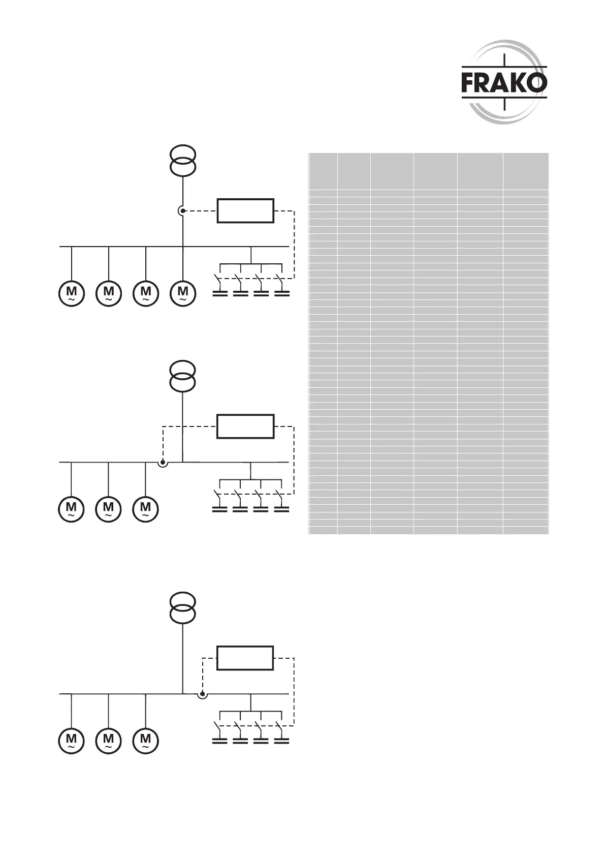
Fig. 1: Correctly installed current transformer registers load current and
capacitor current
reactive power
control relay
Fig. 2: Incorrect! The current transformer only registers the load current:
the capacitor bank is switched in but not out again. Automatic calibration of
the reactive power control relay is not possible!
reactive power
control relay
Fig. 3: Incorrect! The current transformer only registers the capacitor cur-
rent: the capacitor bank is not switched in. The reactive power control relay
gives the message “I = 0” (no current in transformer circuit)!
Reactive power control relays: RM 9606, RM
2106, RM 2112, EMR 1100 S and EMR 1100
To avoid reactive power penalty charges, the reactive power cont-
rol relay must be set, as a minimum requirement, at the target va-
lue of cos ϕ required by the local utility company. The basic factory
settings represent the most frequently specied cos ϕ requirement.
A detailed description of the possible control characteristics is gi-
ven in the operating manual for the reactive power control relay.
Automatic detection of connection, switching sequence and
response current.
The reactive power control relays automatically detect the connec-
tion (phase position), the switching sequence and the response
current (c / k). These instruments have a factory setting of 0.92 for
the target power factor. If it is desired to operate at this power fac-
tor, no further setting is necessary when commissioning the reac-
tive power control relay.
When the AC supply voltage is applied to the instrument for the
rst time, the reactive power control relay carries out the connec-
tion and response current detection process, and is then ready to
operate.