Power Factor Correction Systems
Assembly instruction
Switch board cabinets
The maximum ambient temperature of power factor correction
systems must not exceed 40 °C (EN 60439-1, VDE 0660 T500).
The switch boards must have sufcient air bleeds in the door as
well as in the roof of the cabinet in order to carry off dissipation
heat.
In most cases choked power factor correction systems require a
forced ventilation with a motor fan.
Cabinets built in protection class IP 54 have to be equipped, in
most cases, with lter fans, even if they are unchoked.
Capacitors and combined capacitor / reactor modules of the type C
have been constructed for different widths and depths of cabinets:
The C - modules are inserted in the cabinet on module rails and
xed on them with the screws that have been supplied along with.
Cabinets with a larger depth than the minimum depth, have se-
veral xing positions on the module rails. When using one of the
xing positions at the back, the xing straps at the front have to be
bent to the outside. At the mounting rails there are also xing pos-
sibilities for cable channels for the control circuit. The xing straps
needed can for this purpose be bent out.
The module rails for the different types of cabinets have to be or-
dered separately.
When choosing the type of switch board the weights of the modu-
les have to be taken into consideration, in order to make sure that
a cabinet with a sufcient stability is chosen.
Power loss
The loss power of the modules consisting of the loss power of the
capacitors, resp. choke coils, fuses, contactors and wiring is esti-
mated as follows:
Unchoked modules
or power factor correction systems max. 2.5 W / kVAr
Choked modules
or power factor correction systems max. 8.5 W / kAVr
The switch board cabinet has to be designed in a way that the
loss power can be eliminated and the temperature of the housing
does not exceed 60 °C.
Type min. width of the cabinet min. depth of the cabinet
C64
600 mm 400 mm
C65 600 mm 500 mm
C66 600 mm 600 mm
C84 800 mm 400 mm
C85 800 mm 500 mm
C86 800 mm 600 mm
Set up of power factor correction systems
with C - modules
A modular power factor correction system consists of the following
components:
n
cabinet
n complete power factor control relay package (STR-...)
n mounting plate for the control unit
n capacitor module(s) or capacitor / reactor module(s) including
control-connecting wires (part of the modules)
n
module rail(s) for modules, also needed for the mounting plate
of the control unit
n
fan package
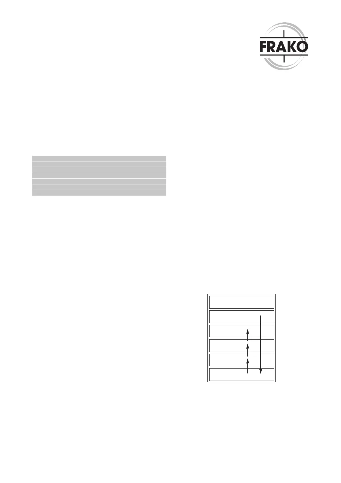
Power Factor Correction systems with several modules are equip-
ped from bottom up. This sequence also applies for the wiring of
the contactor control.
From the control terminal strip a cable, or the corresponding num-
ber of single conductors, has to be laid to the relay (already pre-
mounted in case the complete power factor control relay package
has been ordered). From the control terminal strip he control
wires (supplied with the modules) must be laid to the capacitor
module(s). In case several contactors should be switched parallel,
it will be done by using clamp bridges on the module plugs or with
single conductors from the control terminal strip to the capacitor
module(s).
With this kind of set up an extension at a later time is easy to hand-
le. The set up is shown below. Slot 0 is left empty and serves as
the cable terminal compartment. If required, audio frequency re-
jectors will be installed here.
The rst module has to be put in slot 1. Slot 4 remains empty in
case systems are only equipped with, for example, 3 modules. An
extension at a later time is possible with low effort. Provided that
the cross sections have been sufciently dimensioned for the ex-
tension, the cables for the feeder remain unchanged.
control unit
slot 4
slot 3
slot 2
slot 1
slot 0