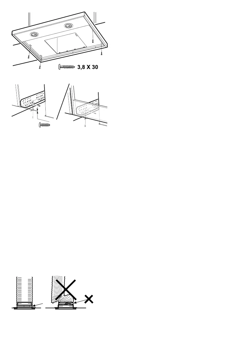
Fig. 3
Fig. 4
The cooker hood can be placed under, be-
tween or built into cupboards. When instal-
led under cupboards, the cooker hood is
screwed into place with four 3.8 x 30
screws, Fig. 3. When placed between or
built into cupboards, the cooker hood is in-
stalled with the aid of brackets. Brackets
and cooker hood must be screwed into pla-
ce with eight 3.5 x 13 screws, Fig. 4. The
brackets are screwed into place with the
bevelled corners facing out and level with
the front edge of the cupboard, Fig. 4A, or
with the bracket facing the front section of
the hood upper cupboard, Fig. 4B. The coo-
ker hood is then screwed into the brackets.
Reinstall filter.
Connection to exhaust flue
Connect the cooker hood with a pipe or
tubing Ø160 mm. If the connection is
Ø125 mm a reducing coupling sleeve must
be used.
Fig. 5
Attention!
When using connecting tubing, the tub-
ing must be stretched and installed di-
rectly adjacent to the connection, Fig. 5.
Removal of protective plastic
Remove all protective plastic from the filter
and any other parts of the product.
12
991.0357.831/D000000006694/180163/2021-09-24