FRANKIA OPERATING MANUAL30 FRANKIA OPERATING MANUAL 31
Electrical board:
The electrical board is located in the rear storage compartment (depending on the floor plan). All body-specific circuits
are protected here.
A) Additional distribution chassis (Mirror heater,
window regulator, rear view camera, etc.)
B) 12V-distribution DS 470
C) Solar charge controller PRS 300 Bus (option)
(For Power Package and Platin Edition see chapter
4.6 or 4.7)
D) 230V distribution with automatic circuit breaker
and residual current circuit breaker (2 x present
with optional inverter)
E) CB 522 charger (2 x present for 2 main body
batteries)
Vehicle electrical system 230V:
For the electrical installation, an initial commissioning test is carried out by a qualified electrician in accordance with
DIN VDE 0100-600 when assembling every FRANKIA motorhome. If the system is expanded or changed, this test must
be repeated. The test report is enclosed with the vehicle documents including a circuit diagram for the 230V installation.
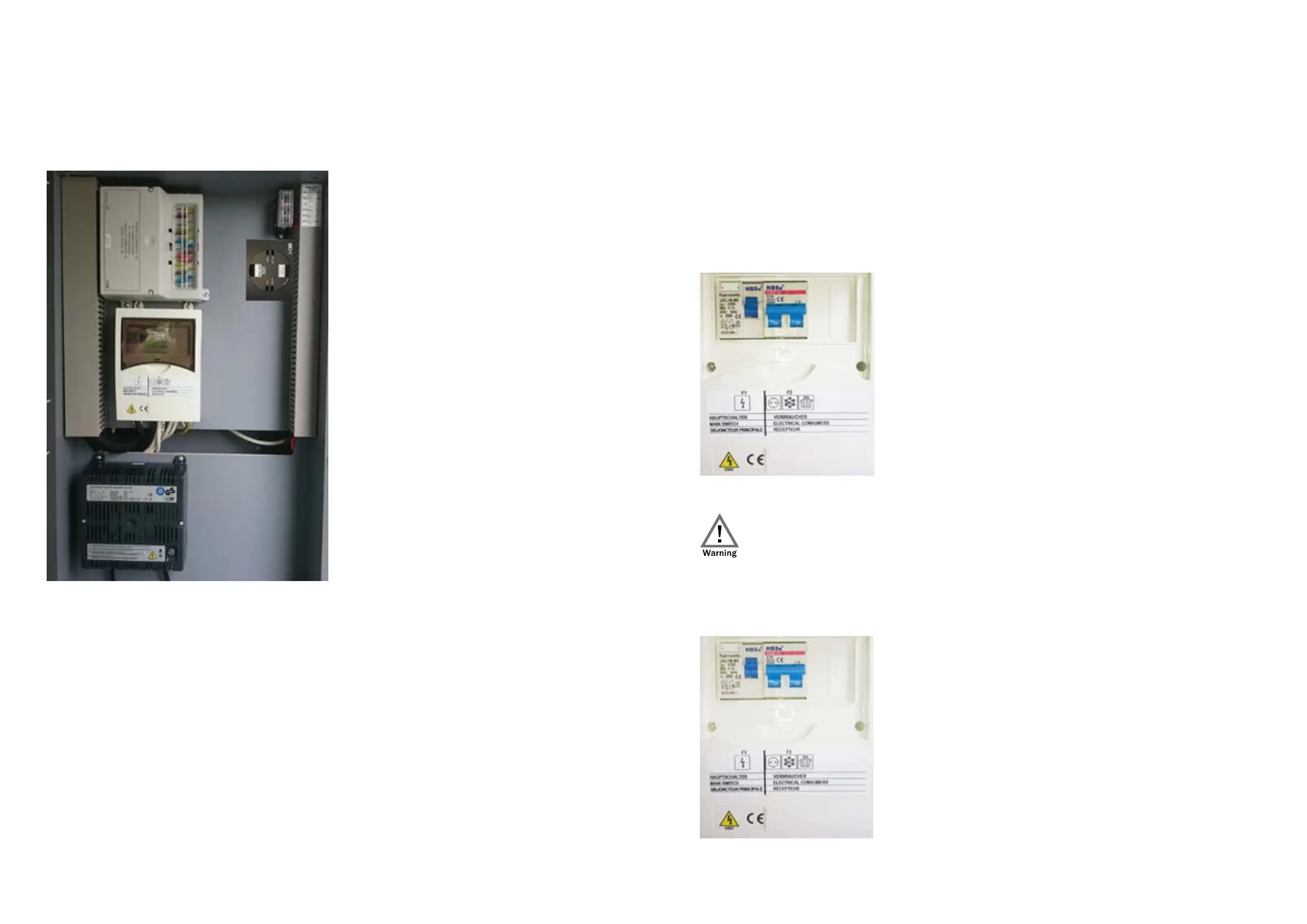
Automatic circuit breaker:
This device protects the 230V connection against overload and short circuit.
Residual current circuit breaker (RCD):
The residual current circuit breaker protects against impermissibly high contact voltages and also serves to prevent fire
in the event of a technical defect. The residual current circuit breaker must be tested monthly to ensure the operational
function and when changing location (pressing the test button simulates a fault to ensure proper functioning - see page
35,36).
A
C
B
D
E
Vehicles with an optional inverter are equipped with two circuit breakers and two residual current circuit breakers.
• By means of the first unit (F1) large consumers such as the refrigerator, heating etc. as well as the in-
put side of the inverter are protected. These are only active with a shore power connection.
• The second unit (F01) is located on the output side of the inverter. All 230V sockets are protected by
this. This unit is active with both shore power and inverter supply.
Operation of the circuit breaker:
Switch off the circuit breaker
• Set the toggle switch to “0”
Switch on the circuit breaker
• Set the toggle switch to “1”
• The circuit breaker is mostly triggered by a defective electrical device. If necessary, have the device
checked and repaired by a specialist.
• The toggle switch must never be held in position “1” by force!
Checking the residual current circuit breaker (RCD):
Test residual current circuit breaker
• Press the test button
• Toggle switch must jump to “0”
Switch on the residual current circuit breaker
• Set the toggle switch to “1”