FRANKIA OPERATING MANUAL52 FRANKIA OPERATING MANUAL 53
Avoid frequent discharges below 30%. The same applies to LiFePo batteries, the greater the depth of di-
scharge, the shorter the lifespan of the batteries. However, these batteries do not have to be fully charged
or recharged permanently and are usable in a partially charged state between 30% and 100%.
To prevent damage to the LiFePo battery, there are several protective devices:
• At very low temperatures below 0°C, the performance of the charging systems is reduced and, if
necessary, completely interrupted from -20°C. This also applies to very high temperatures above
50°C. In both cases, charging starts again automatically when the battery warms up or cools down again.
• Battery capacity warning: Please note the battery capacity indicator on your battery computer. If the
usable capacity falls below 30%, a flashing display should indicate that less than 30% of the battery
capacity can still be used and should be recharged if necessary.
• Automatic battery shutdown: Deep discharge, permanently too high currents, too high temperatures, as
well as incorrect charging voltages can lead to the automatic switching off of the LiFePo battery for its
protection! If the switch-off criterion no longer exists or charging takes place, the battery switches on
again automatically and can be used normally. Please note that specific settings may then be required in
your on-board electronics.
• The on-board battery must be replaced with the same type and specification as the originally installed
on-board battery, or as specified by the manufacturer.
• When expanding the existing LiFePo battery with an additional battery, it is essential that both batteries
are charged 100% independent from each other before they are connected in parallel!
Solar module:
The 4 installed solar modules are BlackLine solar modules with very high efficiency MultiCell technology. The solar
modules have a total output of 400Wp. The solar panel is located on the vehicle roof and converts light into electrical
energy. The energy obtained in this way is fed directly into the 12-volt on-board electrical system, and the on-board
battery is charged if there is an excess. The solar controller takes over the distribution of the solar power.
Maintenance and care of the solar modules:
• The solar cells are protected by a hardened glass plate. The panel is waterproof and weatherproof. Solar
cells must be clean in order to maintain their performance. Therefore, you should clean the glass plate of
the module with a damp cloth and a little washing-up liquid every 4 weeks.
• In dusty environments, the solar panel should be cleaned more often.
• In winter, the panel must be kept free of snow, as covered solar cells cannot supply electricity.
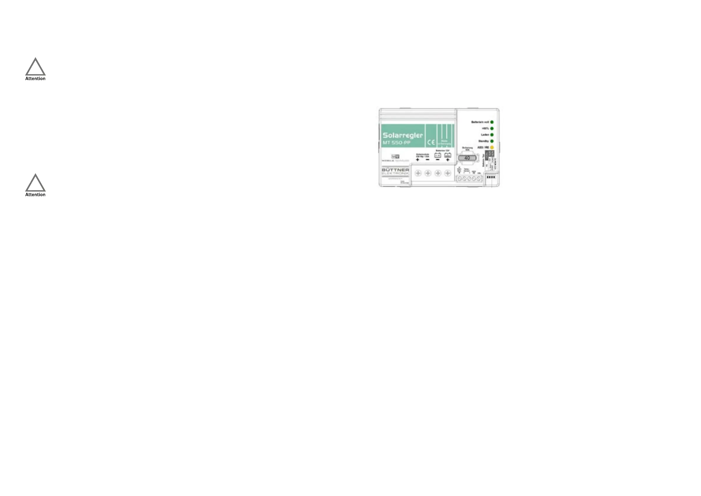
Solar controller:
The installed solar controller is an MT-550-PP (Power-Plus) controller, which is designed for a total solar power of up to
550Wp. The controller takes over the control of the current coming from the solar panels into the 12V power network
and the charging of the on-board batteries.
Operating indicators:
• “AES/RE” (yellow):
◦ Lights up: There is sufficient excess solar power, the “AES/RE” output is activated.
◦ Off: Output “AES/RE” is switched off.
• “Standby” (green):
◦ Flashes: The controller is in standby when no solar power is flowing (at night).
• “Laden/ Charging” (green):
◦ Lights up: Brightness from a slight glow to full brightness indicates the charging current.
◦ Off: Not enough solar energy available.
◦ Flashes: Battery protection safety mode: Battery temperature <-20/-30 °C or overtemperature +50 °C.
Automatic return and recharge at 2 °C lower.
◦ Flashes 1x: Shutdown solar overvoltage: Load LED flashes 1x, then the controller switches to standby
mode. The solar module voltage (Voc) must be checked!
• “> 80%” (green):
◦ Lights up: On-board battery is almost fully charged. Solar controller is in the U1 charging phase.
• “Batterie voll/ Battery/batteries full” (on-board batteries fully charged, green):
◦ Lights up: Battery/batteries 100% charged, charge retention U2, finished.
◦ Glows: The main charging process is still in the U1 charging phase.
◦ Off: The main charging process is still in the I-phase.
If there is no solar power (at night), the operational readiness of the controller is indicated by a brief flashing of the
“Charge” LED (light emitting diode). A steadily flashing “Charge” LED indicates a possible fault in the system: Controller
overheated or a fault found in the self-test, battery too hot (> 50 °C) when using the battery temperature sensor. As
soon as there is sufficient solar power, the “Charge” LED lights up and the charging process begins. The brightness of
the “Charge” LED is also a measure of the solar power implemented: The brighter, the more of the available (even low)
solar power is passed on.