INSTALLATION PLANNING
Typical Submersible Constant Pressure System
11
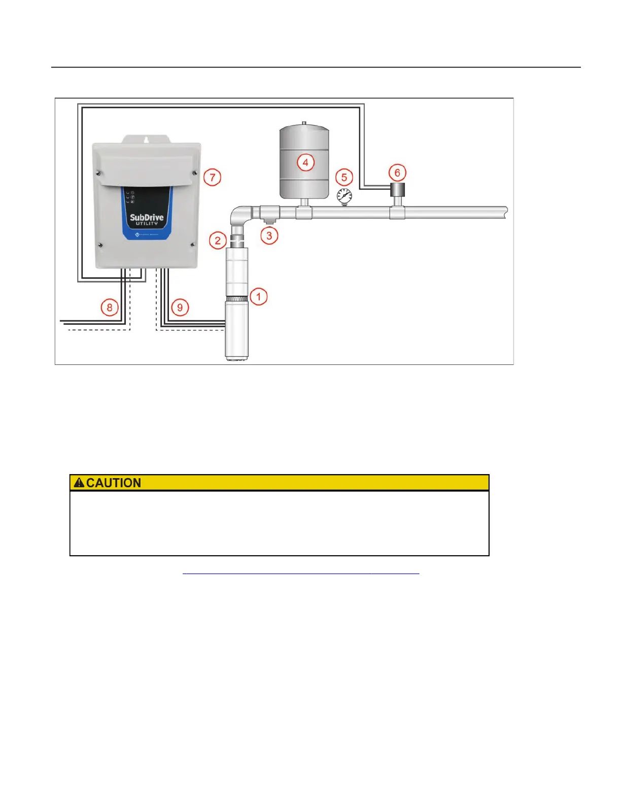
Typical Submersible Constant Pressure System
The above drawing illustrates how a typical submersible pump system should be arranged for a constant
pressure application.
1. Pump and Franklin Electric Motor. Refer to the Franklin Electric AIM Manual for pump, pipe, and cable
sizing information.
2. Check Valve
3. Pressure Relief Valve: Pressure relief valve must be able to pass full pump flow at or above 100 PSI.
4. Pressure Tank: Refer to “
Minimum Pressure Tank and Supply Pipe Sizing” on page 13.
5. Pressure Gauge
6. Pressure Sensor or transducer: Install in a vertical position.
7. UT3P Drive
8. Power Supply from Circuit Breaker. Single phase 3-wire, 230 VAC ±10%.
9. Power to Motor: 230 VAC, Single phase 3-wire or three phase.
A tank tee is recommended for mounting the tank, pressure sensor (or pressure transducer), pressure
gauge, and pressure relief valve. If a tank tee is not used, the pressure sensor or pressure transducer should
be within 6 feet (1.8 meters) of the pressure tank to minimize pressure fluctuations. There should be no
elbows between the tank and pressure sensor.
Risk of bodily injury or property damage.
• Pumps can develop very high pressure in some situations. Always install a pressure relief valve able
to pass full pump flow at or above 100 psi.
• Install the pressure relief valve near the pressure tank and route to a drain capable of full system flow.
 Loading...